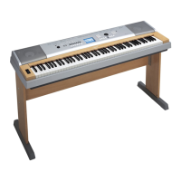
Do you have a question about the Yamaha Portable Grand YPG-635 and is the answer not in the manual?
| Keyboard | 88 keys, Graded Hammer Standard (GHS) keyboard |
|---|---|
| Preset Songs | 30 |
| Amplifiers | 6W + 6W |
| Touch Sensitivity | Hard/Medium/Soft/Fixed |
| Styles | 160 |
| Fingering | Multi Finger, Full Keyboard |
| Style Control | Intro, Main x 2, Fill-in, Ending |
| Music Database | 305 |
| One Touch Setting (OTS) | Yes |
| Data Capacity (Recording) | Approx. 30, 000 notes |
| Compatible Data Format (Playback) | SMF |
| Recording Function | Yes |
| Metronome | Yes |
| Tempo Range | 32 - 280 |
| Transpose | -12 to 0, 0 to +12 |
| USB to Host | Yes |
| Headphones | Yes |
| Voices | 500 voices (including 12 drum/SFX kits) |
| Display | 320 x 240 dots LCD |
| Speakers | 12cm x 2 |
| Featured Voices | Live! Grand Piano |
| Effects | Reverb, Chorus, DSP |
| Songs (Recording) | 5 Songs |
| Compatible Data Format (Recording) | SMF |
| Tuning | 414.8 ~ 440.0 ~ 446.8 Hz |
| Power Supply | PA-150 or an equivalent recommended by Yamaha |
| Connectivity | USB TO HOST |
| Included Accessories | Music Rest |
| Polyphony | 64 notes |
Service requirements, static discharge, chemical, and safety precautions.
Details on keys, display, panel layout, and controls.
Specifications for voices, styles, database, functions, and effects.
Details on songs, MIDI, connectivity, dimensions, and accessories.
Diagram showing major internal components and their interconnections.
Description and numbering of all front panel buttons and controls.
Description of rear panel ports for power, USB, audio, and pedals.
Visual representation of circuit board placement in different assemblies.
Step-by-step guide to removing the lower case assembly.
Detailed steps for removing various circuit boards.
Disassembly of keyboard assembly and its key mechanisms.
Detailed pin description for the UPD789022GB-A15-8E CPU.
Detailed pin description for the S1D13700F01A100 LCD controller.
Block diagrams for logic gates, power switches, converters, and amplifiers.
Required equipment, setup, and procedure to enter diagnostic mode.
Steps to select, execute, and interpret diagnostic test results.
Procedures for resetting settings and clearing user data.
Steps for connecting USB memory and accessing file operations.
Details on MIDI messages transmitted and recognized by the instrument.
Format details for MIDI messages, control changes, and system exclusives.
Diagram and part numbers for upper and lower case assemblies.
Diagram and part numbers for keyboard, wheel, and stand components.
Circuit diagrams for AM, DJACK, DM, MVR, PB, PJK, PSW, TW components.
Diagrams for power supply, CPU, and memory interfaces.
Circuit diagrams for ENC, GHL, PNL, PNR components.
Diagram illustrating signal paths within the keyboard assembly.