EasyManua.ls Logo

Yamaha Portatone PSR-E213 User Manual

Yamaha Portatone PSR-E213
37 pages
To Next Page IconTo Next Page
Page #1 background imageLoading...
Page #1 background image
SERVICE MANUAL
SPECIFICATIONS (総合仕様).................................................................. 3/4
PANEL LAYOUT (パネルレイアウト)......................................................... 5
CIRCUIT BOARD LAYOUT & WIRING (ユニットレイアウト&結線図)........ 7
BLOCK DIAGRAM (ブロックダイアグラム).............................................. 8
DISASSEMBLY PROCEDURES (分解手順)............................................... 9
LSI PIN DESCRIPTION (LSI端子機能表).................................................. 15
IC BLOCK DIAGRAM (ICブロック図)...................................................... 16
CIRCUIT BOARDS (シート基板図)........................................................... 17
TEST PROGRAM (テストプログラム)................................................ 20/22
MIDI IMPLEMENTATION CHART
(MIDIインプリメンテーションチャート)............................................. 24/25
MIDI DATA FORMAT................................................................................. 26
PARTS LIST
OVERALL CIRCUIT DIAGRAM (総回路図)
CONTENTS (目次)
PK 001775
Copyright (c) Yamaha Corporation. All rights reserved. 07.04
HAMAMATSU, JAPAN
PSR-E213: 200702-xxxxxx
PSR-E213
YPT-210
* YPT-210 is an overseas export model. (YPT-210は、輸出専用モデルです。)

Other manuals for Yamaha Portatone PSR-E213

Question and Answer IconNeed help?

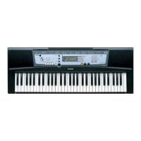
Do you have a question about the Yamaha Portatone PSR-E213 and is the answer not in the manual?
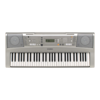
Yamaha Portatone PSR-E213 Specifications

General IconGeneral
Keys61
Polyphony32
Styles100
DisplayLCD
MIDIYes
Speakers2 x 2.5W
EffectsReverb, Chorus
Power Supply9V DC
ConnectionsSustain Pedal

Summary

IMPORTANT NOTICE

SPECIFICATIONS

Keyboards

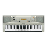
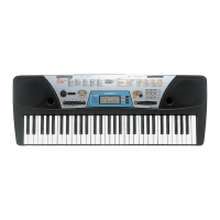
Details the 61 standard-size keys (C1-C6).

Panel Controls

Lists all buttons and controls on the front panel.

Voice & Style Features

Describes sound capabilities and musical style features.

Dimensions & Weight

Provides the physical dimensions and weight of the instrument.

PANEL LAYOUTS

Front Panel Layout

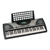
Identifies controls and features on the front panel.

Rear Panel Layout

Identifies ports and connectors on the rear panel.

DISASSEMBLY PROCEDURES

Lower Case Assembly

Step-by-step guide for removing the lower case.

Component Removal Steps

Procedures for removing boards like DMLCD, PNAM, and keyboard.

TECHNICAL DIAGRAMS AND DESCRIPTIONS

Circuit Board Layout & Wiring

Shows diagrams and connections for circuit boards.

Block Diagram

Illustrates the functional blocks of the instrument's circuitry.

LSI Pin Description

Details the functions of LSI pins for the CPU.

Circuit Board Diagrams

Shows layout diagrams for DMLCD and PNAM circuit boards.

OPERATIONAL FEATURES

Test Program

Guide to performing diagnostic tests on the instrument.

MIDI Implementation

Details MIDI communication protocols and capabilities.

PARTS LIST & SCHEMATICS

Parts List

Comprehensive list of all replaceable parts for the instrument.

Overall Circuit Diagram

Provides the complete schematic diagram of the instrument's circuitry.

Related product manuals