ABCDEFGH
1
2
3
4
5
6
IJKL
7
8
RX-397
30
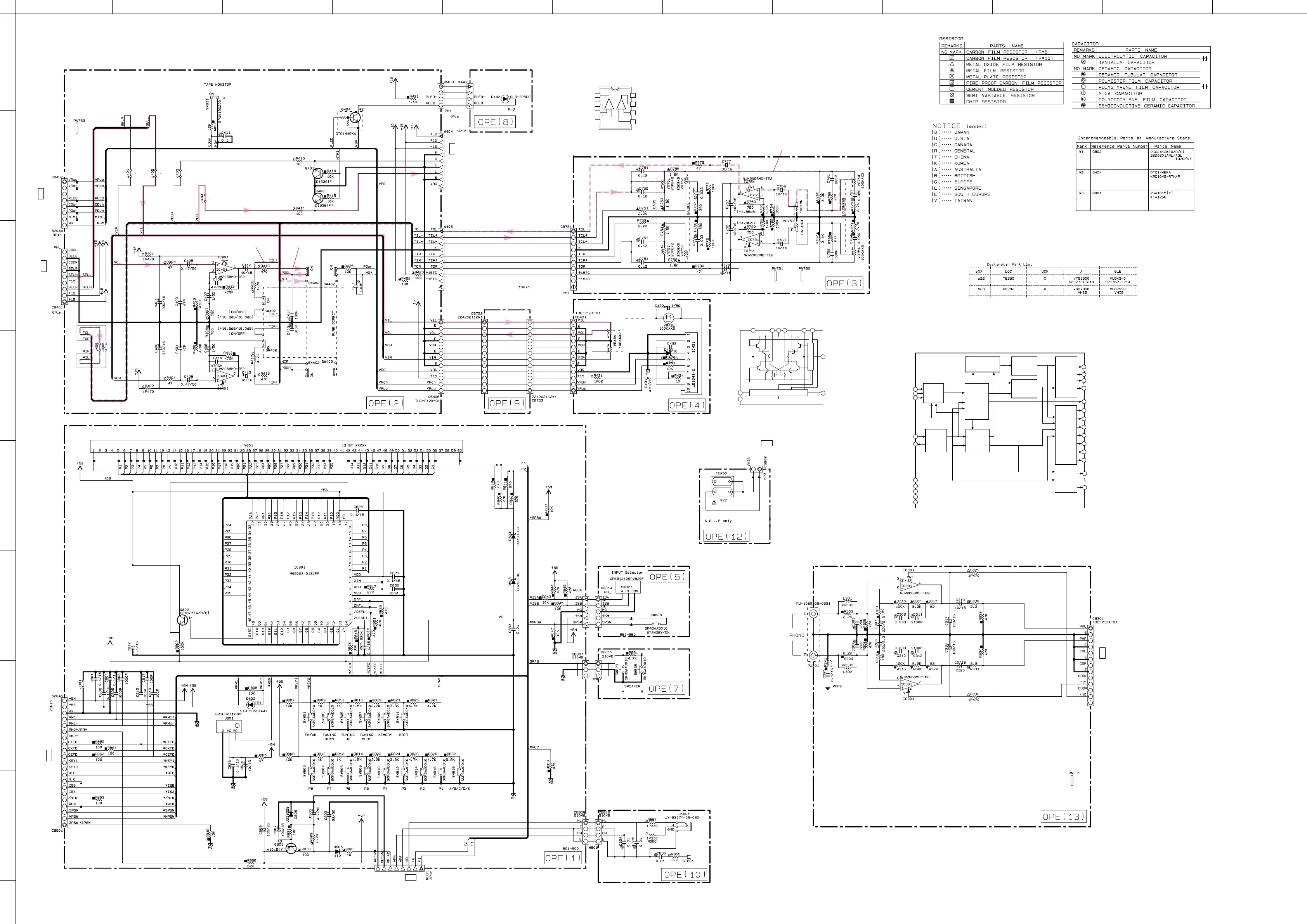
■ SCHEMATIC DIAGRAM (OPERATION)
*
All voltages are measured with a 10M
Ω
/V DC electronic volt meter.
* Components having special characteristics are marked
Z
and
must be replaced with parts having specifications equal to
those originally installed.
* Schematic diagram is subject to change without notice.
13.1
14.5 13.1
-14.4
-14.4
0
0
0
0
0
0
0.1
0.1
0.6
0.6
0.8
0.8
1.8
1.8
14.1
14.0
-14.0
14.1
1.4
0
0
0
0
0
0
0.1
0.1
0.1
-15.7
-12.7
-12.8
-19.7
-19.6
-13.1
-21.4
-21.4
-21.4
-21.4
-21.4
-19.6
-19.6
-19.3
-14.4
-14.4
-14.8
-15.8
-13.9
-13.9
-19.8
-19.8
-19.8
-19.8
-19.8
-19.8
-19.8
-19.8
-19.8
-19.8
-19.8
-19.8
-19.8
-19.8
-19.8
-15.7
-16.0
-18.8
-18.8
-21.6
-21.2
4.8
-21.4
-21.4
-21.4
-13.1
-19.9
~
~
-12.7
4.8
4.7
4.7
4.7
4.7
2.1
0
2.1
-14.4
-19.6
-19.8
0
0
0
0
0
0
0
12.6
-12.6
0
-22.3
-22.3
-21.6 -27.7 -27.7
-28.8
-19.4
-21.3
-19.3
-14.8
-15.8
-13.9
-12.7
-12.7
-13.9
-12.4
-12.7
-12.7
-21.4
-21.3
-21.2
-21.2
-21.2
-21.3
-21.4
-21.4
-21.4
-21.4
4.8
4.8
4.8
0
-14.4
-19.6
-19.8
-19.8
-19.8
-19.8
-19.8
-19.8
-19.8
-19.8
-19.8
-19.8
-19.8
-19.8
-19.8
-19.8
-19.8
-21.6
-19.6
~
~
~
~
~
~
-21.3
-21.4
~
~
~
~
~
~
~
~
0.1
0
PURE DIRECT ONPURE DIRECT OFF
PURE DIRECT OFF
TO FUNCTION (2) CB611
Page 29 D-4
TO FUNCTION (2) W601
Page 29 D-4
TO MAIN (1) CB107
Page 31 A-6
TO MAIN (2) W293
Page 31 J-5
TO FUNCTION (2) CB607
Page 29 H-3
TO FUNCTION (2) CB606
Page 29 F-3
TO MAIN (1) CB103
Page 31 B-2
I
C431
: LB1641
Motor Driver
23
P1
5
IN 1
1
GND
4
VZ
6
IN 2
OUT 1
8
VCC 2
10
OUT 2
9
P2
INPUT LOGIC
PRE DRIVER
7
VCC 1
I
C301, 401, 751
: NJM2068MD-TE
Dual OP-Amp
–+
OUT
1
–IN
1
–V
CC
+V
CC
OUT
2
1
2
3
4
5
+IN
1
–IN
2
+IN
2
–+
6
7
8
I
C801
: M66003-0131FP
Display Driver
52
Display
controller
Segment
digit
select/
output
circuit
Serial
receive
circuit
Digit
output
circuit
Clock
generator
DIG11/
SEG42
51
DIG12/
SEG41
50
DIG13/
SEG40
49
DIG14/
SEG39
48
DIG15/
SEG38
47
DIG16/
SEG37
46
DIG17/
SEG36
45
SEG35
XOUT
6
Vcc1
8
Vcc2
18
Vss
5
Vp
64
XIN
7
CS
SCK
3
SDATA
4
RESET
1
SEG00
44
9
SEG34
SEG26
17
19
SEG25
Segment
output
circuit
Display code
RAM
(8-bit x 60)
CGROM
(35 bit x 166)
CGROM
(35 bit x 16)
code
select
Code
write
Code/
command
control
circuit
DIG00
63
53
DIG10
2
data
timing
clock
dot data
write
scan pulse


 To Next Page