EasyManua.ls Logo

Yamaha RX-V363 Service Manual

Yamaha RX-V363
99 pages
To Next Page IconTo Next Page
Page #1 background imageLoading...
Page #1 background image
SERVICE MANUAL
101084
IMPORTANT NOTICE
This manual has been provided for the use of authorized YAMAHA Retailers and their service personnel.
It has been assumed that basic service procedures inherent to the industry, and more specifically YAMAHA Products, are already
known and understood by the users, and have therefore not been restated.
WARNING:
Failure to follow appropriate service and safety procedures when servicing this product may result in personal
injury, destruction of expensive components, and failure of the product to perform as specified. For these reasons,
we advise all YAMAHA product owners that any service required should be performed by an authorized
YAMAHA Retailer or the appointed service representative.
IMPORTANT:
The presentation or sale of this manual to any individual or firm does not constitute authorization, certification or
recognition of any applicable technical capabilities, or establish a principle-agent relationship of any form.
The data provided is believed to be accurate and applicable to the unit(s) indicated on the cover. The research, engineering, and
service departments of YAMAHA are continually striving to improve YAMAHA products. Modifications are, therefore, inevitable
and specifications are subject to change without notice or obligation to retrofit. Should any discrepancy appear to exist, please
contact the distributor's Service Division.
WARNING:
Static discharges can destroy expensive components. Discharge any static electricity your body may have
accumulated by grounding yourself to the ground buss in the unit (heavy gauge black wires connect to this buss).
IMPORTANT:
Turn the unit OFF during disassembly and part replacement. Recheck all work before you apply power to the unit.
CONTENTS
TO SERVICE PERSONNEL .......................................... 2
FRONT PANELS ........................................................ 3–4
REAR PANELS .......................................................... 4–9
REMOTE CONTROL PANELS ...................................... 9
SPECIFICATIONS.................................................. 10–12
INTERNAL VIEW ......................................................... 13
DISASSEMBLY PROCEDURES ........................... 14–16
UPDATING FIRMWARE ........................................ 17–19
SELF DIAGNOSTIC FUNCTION ........................... 20–37
DISPLAY DATA ..................................................... 38–39
IC DATA ................................................................. 40–55
BLOCK DIAGRAMS .............................................. 56–57
PRINTED CIRCUIT BOARDS................................ 58–71
PIN CONNECTION DIAGRAMS .................................. 72
SCHEMATIC DIAGRAMS ...................................... 73–83
REPLACEMENT PARTS LIST .............................. 85–95
REMOTE CONTROL.............................................. 96–98
Advanced setup ........................................................... 99
P.O.Box 1, Hamamatsu, Japan
2008 All rights reserved.
This manual is copyrighted by YAMAHA and may not be copied or
redistributed either in print or electronically without permission.
'08.02
RX-V363/HTR-6130
AV RECEIVER
DIGITAL HOME THEATER SYSTEM
YHT-290/195
YHT-290 consists of HTR-6130 and NS-P270D. (C model)
YHT-195 consists of HTR-6130 and NS-P270D. (R, K, A, L models)
NS-P270D consists of NX-E270, NX-C270 and SW-P270.
This service manual is for RX-V363/HTR-6130.
For NX-E270, NX-C270 and SW-P270 service manual, please refer to the following service manual:
NX-P270/NX-P276: 101000
RX-V363/HTR-6130
本资料由OKXIA视听皮带资源库www.okxia.cn提供
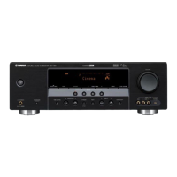
Table of Contents

Other manuals for Yamaha RX-V363

Questions and Answers:

Yamaha RX-V363 Specifications

General IconGeneral
Channels5.1
Frequency Response10Hz - 100kHz +0, -3dB
Signal-to-Noise Ratio100 dB (CD)
Audio DecodingDolby Digital, DTS
HDMI Inputs2
HDMI Outputs1
Component Video Inputs/Outputs2/1
Digital Audio Inputs2 Optical, 1 Coaxial
Multi-Channel Input6-channel
Subwoofer Output1
Headphone Output1
Remote ControlYes
FM/AM TunerYes
Audio D/A Converter24-bit/192kHz
Built-in DecodersDolby Digital, DTS
Surround Sound EffectsYes
Digital Sound Processor (DSP)Yes
DSP Presets8
Tuner BandsFM/AM
Preset Station Qty40
Input Sensitivity/Impedance200 mV/47 kOhms
Dimensions435 x 151 x 315 mm
Weight8 kg
Additional FeaturesCINEMA DSP, Night Listening Enhancer
Tuning RangeFM: 87.5-108 MHz, AM: 530-1710 kHz
Total Harmonic Distortion0.06% (20 Hz-20 kHz, 40 W, 8 ohms)
Analog Audio Inputs5 (RCA)
Speaker Terminals5

Summary

To Service Personnel

Chemical Content Warning

Notice regarding chemicals known to cause cancer or reproductive harm.

Technical Specifications

Audio Section Specifications

Details audio output power, headroom, impedance, and frequency response.

Sound and Surround Select Menu

Set Menu Table Navigation

Basic Setup Menu Options

Configures basic system parameters like speaker settings, levels, and distances.

Manual Setup Options

Provides detailed manual configuration for speakers, levels, and crossover.

Disassembly Procedures

Component Board Removal

DSP P.C.B. Removal

Instructions for detaching the Digital Signal Processor board.

Printed Circuit Board Inspection

PCB Checking Guidelines

Guidelines for inspecting and connecting PCBs during service.

Firmware Update Process

Firmware Update Operation Procedures

Step-by-step guide for performing firmware updates.

Self-Diagnostic Function

Speaker Set Configuration

Configures speaker settings (size, crossover, tone).

Diagnostic Menu Items

ROM Version and Checksum

Displays firmware version and checksums, and performs memory tests.

Initiating Self-Diagnosis

Starting Self-Diagnostic Mode

Initiates the self-diagnostic mode via button combination.

Canceling Self-Diagnostic Mode

Procedures to exit self-diagnostic mode and restore settings.

Protection Function History and Clearing

Diagnostic Menu Navigation

Diagnostic Menu Operation Guide

Explains how to navigate main and sub-menus in diagnostic mode.

Self-Diagnostic Menu Details

Speaker Set Configuration

Protection Parameter Display

A/D Data Check Function

Factory Preset Initialization

ROM VER/SUM (Firmware Check)

IC Data: Microprocessor and DSP

IC101 ADSP-BF531 CPU Pinout

Pin definitions and block diagram for the DSP microprocessor.

Audio CODEC IC

IC301 AK4588VQ Pinout

Pinout and block diagram for the 2/8-channel audio codec with DIR.

Electronic Volume Control IC

IC161 R2A15218FP Pinout

Pinout for 8-channel volume, selector, and tone control IC.

Block Diagrams

Video, Audio, and Power Supply Block Diagram

Block diagram showing signal flow for video, audio, and power.

Control Sections Block Diagram

Block diagram illustrating control signal paths and microprocessors.

Pin Connection Diagrams

Schematic Diagrams

DSP Schematic Section 1/6

Part of the DSP schematic showing microprocessor, EEPROM, and SDRAM connections.

Operation Board Schematics

Main Board Schematics

Power Amplifier Stages Schematic

Schematic sections for the 3-channel and 2-channel AF power amplifiers.

Replacement Parts List

Circuit Board Parts Lists

Amplifier Unit Assembly

Front Panel Unit Assembly

Remote Control Overview

Remote Control Key Layout

Advanced Setup Operations

Factory Preset Initialization

Resets all unit parameters to initial factory settings.

Related product manuals