EasyManua.ls Logo

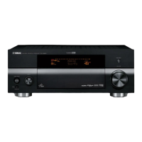
Yamaha RX-V3800 Service Manual

Yamaha RX-V3800
99 pages
To Next Page IconTo Next Page
Page #1 background imageLoading...
Page #1 background image
91
RX-V3800/DSP-AX3800
RX-V3800/
DSP-AX3800
PIN CONNECTION DIAGRAMS
• ICs
1
12
1324
25
36
37 48
1
24
36
37
12
25
13
48
3:VOUT
1:VIN
2:GND
28
14
1
16
8
1
1
4
8
24
12
1
32
16
1
1
4
8
5
1
OUTPUT
INPUT
GND
OUT
COM
IN
+VS
GND
V
OUT
14
7
1
16
8
1
48
13
37
24
1
12
36
25
8
4
1
50
75
76
1
51
25
26
100
36
18
1
50
75
76
1
51
25
26
100
136
37
72
73108
109
144
1
3
4
5
18
9
1
1
4
8
144
45
89
88
132
133
176
116
17
32
3348
49
64
LC89057W-VF4AD-E
ABT1010PQ100A ADV7342BSTZ
SiI9134CTU
ADV7401BSTZ-80
F2621E-01-TR IP00C772DSD1791DBR
AK4384ET BD3841FS
YAC523-EVR2
BA00JC5WT-V5
CD4051BNSR
BA15218F CXB1442AR-T4
ADM222ARZ
D70YE101BRFP266
M3087BFKBGP
M30845MW-001-GP
KIA79M05PI-UKIA7809API-U/P LA7106M-TLM-E
MM74HC4051SJX
MM74HC4053SJX
SN74CBT3253CPWR
LA73054-TLM-E
LA73050-TLM-E
LA73053-TLM-E
LC72722PM
LC709004A-TLM-E
YAC526-EZE2
LC74782JM-8A16-
TLMC
NE5532DR
TC7SET32FU
NJM2885DL1-33NJM2068MD-TE2
LM61CIZ
NJM2581M
TC74VHCU04FT
M24C02-WDW6TP
NJM2867F3-05
TC7SET08FU
TC74VHCT08AFT
TC7SET125FU

Other manuals for Yamaha RX-V3800

Questions and Answers:

Yamaha RX-V3800 Specifications

General IconGeneral
Audio Channels7.1
Amplifier TypeDiscrete
THD (Total Harmonic Distortion)0.04%
Signal-to-Noise Ratio100 dB
HDMI Inputs4
HDMI Outputs2
HDMI Version1.3a
Dolby DigitalYes
DTSYes
Surround SoundYes
Component Video Input3
Component Video Output1
S-Video Input4
S-Video Output1
Composite Video Input5
Composite Video Output1
Digital Audio Input (Coaxial)3
Analog Audio Input6
Weight37.5 lbs
Input Sensitivity200 mV
Power Output140 Watts (8 ohms, 20 Hz - 20 kHz, 0.04% THD, 2 channels driven)
Frequency Response10 Hz - 100 kHz

Summary

Pin Connection Diagrams

Printed Circuit Boards

DSP PCB (Side A)

Layout of the Digital Signal Processor Printed Circuit Board on Side A.

DSP PCB (Side B)

Power Systems

D-VIDEO 1/5

Replacement Parts List

Electrical Component Parts

List of electrical components with warnings and special characteristics.

P.C.B. DSP

P.C.B. FUNCTION

P.C.B. OPERATION

P.C.B. MAIN

P.C.B. POWER

P.C.B. A-VIDEO

P.C.B. D-VIDEO

P.C.B. FL

P.C.B. NET

Overall Assembly

Accessories

Front Panel and Sub Chassis Unit

Amp Unit

Remote Control

Advanced Setup Menu

System Settings

Settings for speaker impedance, remote sensor, and RS-232C.

Schematic Diagrams

DSP 2/3

DSP 3/3

FUNCTION 1/4

FL 1/2

FL 2/2

NET 1/2

NET 2/2

Key Layout

Source-ity Mode for Code

Schematic Diagrams & Remote Control

Related product manuals