EasyManuals Logo

Yamaha wr250f User Manual

Yamaha wr250f
694 pages
To Next Page IconTo Next Page
To Previous Page IconTo Previous Page
Page #396 background imageLoading...
Page #396 background image
4 - 64
ENG
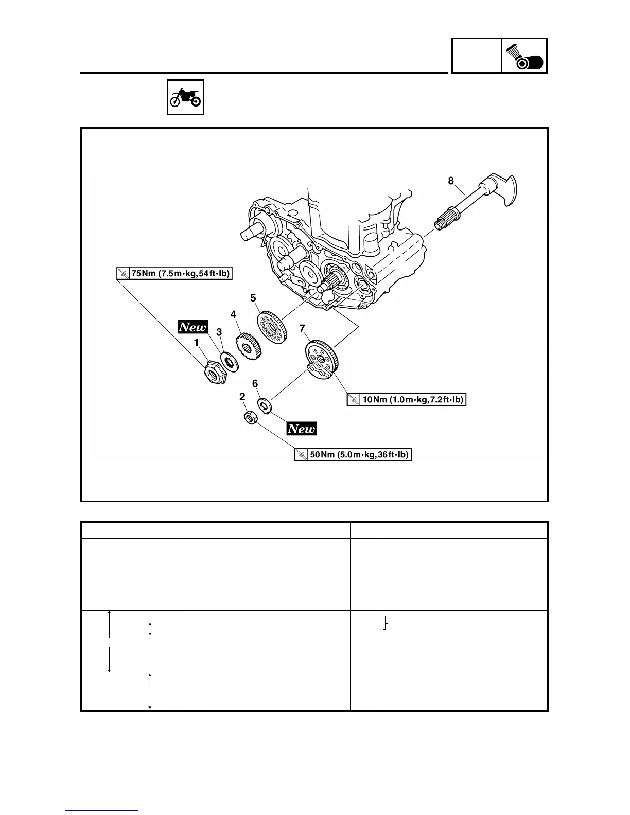
BALANCER
BALANCER
Extent of removal: 1 Balancer shaft drive gear 2 Balancer shaft
Extent of removal Order Part name Q’ty Remarks
BALANCER REMOVAL
Preparation for removal Primary driven gear Refer to “CLUTCH” section.
Right crankcase cover Refer to “OIL FILTER ELEMENT,
WATER PUMP AND RIGHT CRANK-
CASE COVER” section.
Stator Refer to “CDI MAGNETO” section.
1 Nut (primary drive gear) 1
Refer to “REMOVAL POINTS”.
2 Nut (balancer shaft driven gear) 1
3 Lock washer 1
4 Primary drive gear 1
5 Balancer shaft drive gear 1
6 Lock washer 1
7 Balancer shaft driven gear 1
8 Balancer shaft 1 Refer to “REMOVAL POINTS”.
2
1
2

Table of Contents

Questions and Answers:

Question and Answer IconNeed help?

Do you have a question about the Yamaha wr250f and is the answer not in the manual?

Yamaha wr250f Specifications

General IconGeneral
Engine TypeLiquid-cooled, 4-stroke, DOHC, 4-valve
Displacement250cc
Bore x Stroke77.0 mm x 53.6 mm
Fuel SystemFuel injection
IgnitionTCI
Final DriveChain
Tires Front80/100-21
Width32.5 in
Wheelbase58.3 in
Suspension RearKYB® single shock; fully adjustable
Brakes FrontHydraulic single disc
Brakes RearHydraulic single disc

Related product manuals