Do you have a question about the Yamaha YST-SW015 and is the answer not in the manual?
Essential information for safe and proper servicing, including component replacement and leakage testing procedures.
Comprehensive technical specifications including output, input, frequency response, dimensions, and power requirements.
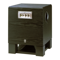
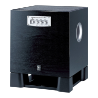
Illustrations of rear panel configurations for U, C, and A regional models.
Step-by-step instructions for safely removing the speaker driver unit from the enclosure.
Procedures for setting up and confirming the auto standby feature's operation using signal generators and LEDs.
Overall schematic showing the functional blocks and signal flow of the subwoofer system.
Detailed electronic schematic diagram of the subwoofer's circuitry, including component connections and values.
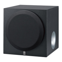
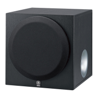
The YST-SW015 is a subwoofer system designed to enhance the low-frequency audio output of a home entertainment setup, providing a richer and more immersive sound experience. This device leverages Yamaha's Advanced Active Servo Technology, which combines a negative-impedance converter power amplifier with a high-compliance woofer to achieve powerful and accurate bass reproduction. The system is built with a 6.5-inch cone driver, featuring magnetic shielding to prevent interference with other electronic devices, particularly televisions.
At its core, the YST-SW015 functions as a dedicated subwoofer, reproducing the deep bass frequencies that smaller, full-range speakers often struggle with. It receives low-level audio signals from an amplifier or receiver via its RCA pin jack input, processes these signals, and then amplifies them to drive its internal woofer. The system is designed to integrate seamlessly into various audio setups, adding depth and impact to music, movies, and games.
A key feature of the YST-SW015 is its comprehensive control panel, located on both the front and rear of the unit, allowing users to tailor the subwoofer's performance to their specific listening environment and preferences. On the front panel, a STANDBY/ON switch provides immediate power control, while a B.A.S.S. (Bass Action Selector System) switch allows for quick adjustments to the bass characteristics, offering different modes to suit various audio content. A VOLUME control knob enables precise adjustment of the subwoofer's output level, ensuring it blends harmoniously with the main speakers. Additionally, a HIGH CUT control allows users to set the upper frequency limit of the subwoofer, preventing overlap with the main speakers and ensuring a smooth transition between frequency ranges. An LED indicator on the front panel provides visual feedback on the unit's operational status.
The rear panel offers further control and connectivity options. A main POWER switch provides a hard power cutoff for the unit. An Auto Standby Switch offers three settings: HIGH, LOW, and OFF. In HIGH or LOW modes, the subwoofer automatically detects an incoming audio signal and powers on, then enters a standby state after a period of inactivity, conserving energy. The HIGH setting requires a higher input signal to activate, while the LOW setting is more sensitive. The OFF setting disables the auto-standby function, keeping the unit continuously on or off based on the main power switch. A Phase Switch allows users to select between NORM (normal) and REV (reverse) phase, which is crucial for optimizing bass response and preventing phase cancellation issues that can occur when the subwoofer's output is out of phase with the main speakers. For international models (R, T, K models), a Voltage Selector switch is included, enabling the unit to operate with different AC voltage standards (110-120V or 220-240V), providing flexibility for use in various regions.
The internal circuitry of the YST-SW015 includes several key components that contribute to its performance and protection. A low-pass filter (LPF) with a 6dB/octave slope and a high-pass filter (HPF) with a 12dB/octave slope are integrated to manage frequency distribution. The system incorporates a limiter circuit to prevent distortion and protect the driver from excessive signal levels. A protection circuit is also in place to safeguard the unit against potential damage from overcurrent, overheating, or DC offset. The power supply unit ensures stable and clean power delivery to all internal components, while regulators maintain consistent voltage levels. A music sensor circuit is integral to the auto-standby function, detecting audio input to trigger power-on.
The YST-SW015 is designed for ease of use and flexible integration into a variety of audio systems. Its RCA pin jack input allows for simple connection to the subwoofer output of an AV receiver or amplifier. The front-mounted controls for volume, high cut, and B.A.S.S. make it convenient to adjust the sound without needing to access the rear of the unit. The auto-standby feature is particularly useful for energy conservation, as the subwoofer will automatically power on when an audio signal is detected and power off after a period of inactivity, eliminating the need for manual power cycling. The phase switch is a critical tool for optimizing sound quality, allowing users to experiment with different settings to achieve the most coherent and impactful bass response in their listening space. The magnetic shielding of the driver ensures that the subwoofer can be placed near a television or other sensitive electronic equipment without causing visual or audio interference.
Maintenance of the YST-SW015 primarily involves ensuring proper operation and addressing any issues that may arise. The service manual provides detailed instructions for disassembly, allowing authorized service personnel to access internal components for repair or replacement. Critical components, identified with specific markings, must be replaced with parts having identical specifications to ensure continued safe and proper operation.
For safety, the manual emphasizes the importance of leakage current measurement (for 120V models) after any service, ensuring that all exposed conductive surfaces are properly insulated from supply circuits. The use of a meter with an impedance equivalent to 1500 ohms shunted by 0.15µF is specified, and leakage current must not exceed 0.5mA. Technicians are instructed to test for leakage with the AC plug in both polarities.
The manual also includes a warning about static discharges, which can damage expensive components. Service personnel are advised to ground themselves to the unit's ground buss before handling internal parts. It is also crucial to turn the unit OFF during disassembly and part replacement and to recheck all work before applying power.
A "Chemical Content Notice" warns about the presence of lead in solder and other chemicals in electrical/electronic and plastic components, advising against oral contact and prolonged skin exposure to solder. Proper ventilation and eye protection are recommended when soldering, and hands should be washed after contact with solder or internal components.
A specific procedure is outlined for confirming the auto-standby operation, which involves connecting a 10kΩ resistor to R60 on the MAIN P.C.B. (3) to shorten the operation check time, applying a sine wave signal (100Hz, 8mV) from a signal generator to the unit's input, and observing the LED indicator's behavior in both LOW and HIGH auto-standby settings. This allows technicians to verify that the auto-standby function is working correctly.
The disassembly procedures are clearly detailed, starting with the removal of the driver and front panel assembly, followed by the rear panel assembly. Specific instructions are provided for removing screws, disconnecting connectors, and handling delicate parts. For example, an Allen wrench (2.5mm) is required to unscrew the front panel assembly. When checking the P.C.B., all connectors removed during disassembly must be reconnected to their original positions, and the rear panel assembly should be placed on a spread cloth to prevent damage.
The manual also highlights that certain parts, such as the switch knob (SW3) and the power switch (SW4), are bonded to a specific component (3-3). If these parts require replacement, both the switch knob, power switch, and the bonded component (3-3) must be replaced simultaneously and re-bonded using a recommended adhesive (Diabond 1620B). This ensures the structural integrity and proper function of these interconnected parts.
| Subwoofer type | Active subwoofer |
|---|---|
| Subwoofer frequency range | 30 - 200 Hz |
| Product color | Black |
| Power consumption (standby) | 0.8 W |
| Subwoofer depth | 325 mm |
|---|---|
| Subwoofer width | 280 mm |
| Subwoofer height | 320 mm |
| Subwoofer weight | 9200 g |