Do you have a question about the Yamaha YST-SW315 and is the answer not in the manual?
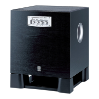
| Driver | 10" cone |
|---|---|
| Frequency Response | 20 Hz - 160 Hz |
| Weight | 19 kg |
| Impedance | 5 Ohms |
| Inputs | Line Level, Speaker Level |
| Outputs | Speaker Level |
Warns about risks of injury and component damage from improper service, advising authorized personnel.
Notes that specifications may change and advises contacting the distributor for discrepancies.
Warns about static discharges damaging components and advises grounding.
Instructs to turn off power during service and recheck work before applying power.
Covers replacement of critical parts and procedures for leakage current measurement after service.
Warns about lead in solder and chemical hazards in components, providing guidance on lead-free solder.
Lists detailed technical specifications of the subwoofer, including output power and dimensions.
Shows an internal view with numbered components and their respective PCB locations for identification.
Displays the signal flow and main functional blocks of the subwoofer's circuitry.
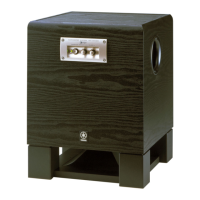
Illustrates the rear panel connections and features for U, C, and A model subwoofers.
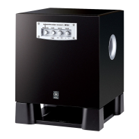
Illustrates the rear panel connections and features for B and G model subwoofers.
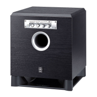
Illustrates the rear panel connections and features for R, T, and K model subwoofers.
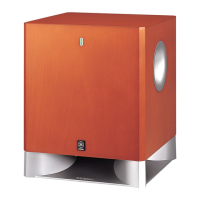
Illustrates the rear panel connections and features for the J model subwoofer.
Details steps for removing the driver unit, including unscrewing and disconnecting.
Outlines steps to remove the front panel assembly, including unscrewing and disconnecting connectors.
Details steps for removing the rear panel assembly, including unscrewing and disconnecting connectors.
Provides instructions for checking the PCB, including reconnecting connectors and placing the unit on a cloth.
Notes that a specific bush must be replaced with a new one after removing the rear panel assembly.
Describes how to confirm power amplifier operation using a signal generator and oscilloscope, checking waveforms at specific points.
Details the normal and abnormal waveform observations for points A and B, including voltage and time settings.
Explains how to perform idling adjustment for amplifier stabilization, including wait times and voltage checks.
Details the procedure to check the auto standby function, including setting the switch and observing LED changes.
Shows part of the schematic, focusing on the power amplifier and test points.
Lists semiconductor component references and their locations on various MAIN PCBs.
Presents the complete schematic diagram, including pin connection details and part types.
Lists electrical components with their part numbers, descriptions, and abbreviations.
Details capacitors C1 through C60, including part numbers, types, values, and markets.
Lists diodes and fuses with their part numbers, types, and markets.
Lists resistors and relays with their part numbers, types, and markets.
Shows an exploded view of the subwoofer assembly and lists mechanical parts with their part numbers and descriptions.
Shows an exploded view of the rear panel assembly and lists mechanical parts with their part numbers and descriptions.