Do you have a question about the Yamatake SDC15 Series and is the answer not in the manual?
| Control Method | PID control |
|---|---|
| Input Type | Thermocouple, RTD, DC voltage, DC current |
| Alarm Output | Relay contact |
| Communication | RS-485 (optional) |
| Mounting | Panel mounting |
| Humidity | 20 to 90% RH (non-condensing) |
| Output Type | Relay |
| Power Supply | 100 to 240 VAC, 24 VAC/DC |
| Control Output | Relay contact |
| Dimensions | 48 x 48 mm |
| Operating Temperature | -10 to 50°C |
| Storage Temperature | -20 to 60°C |
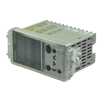
| Type | Digital Controller |
Demonstrates GP-Pro EX communication settings for the first example scenario.
Lists and describes communication parameters configurable within GP-Pro EX.
Explains how to configure communication settings when the display is in off-line mode.
Illustrates the first cable connection diagram for RS-232C device communication.
Shows cable connection for RS-422/485 (4-wire) communication.
Illustrates cable connections for RS-422/485 (2-wire) communication.
Lists device codes and address codes for SDC series devices.
Provides device codes and addresses for DMC, DCP, and CMC series devices.