Do you have a question about the Yamato DP-6900 and is the answer not in the manual?
Data for each weighing capacity, including NTEP and Non-NTEP models.
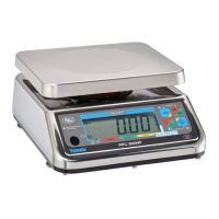
Details the meaning of various indicators on the display panel.
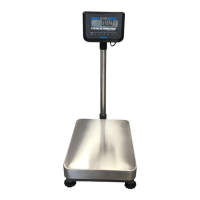
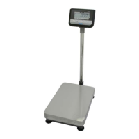
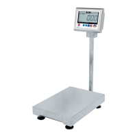
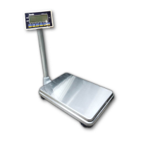
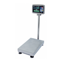
Covers dimensions, weight, materials, and protection rating.
Details power supply, battery life, operating conditions, and options.
Provides detailed dimensional drawings of the scale and its components.
Explains the various signs and indicators on the scale's display.
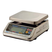
Describes the function of individual keys like ON/OFF, G/N, Set, Tare, Zero Reset.
Explains operations using combinations of keys for setting modes.
Procedure to access the scale's test mode using a deep-set switch.
How to view internal counts, raw counts, and AD converter status.
Checking battery voltage, software version, and display segments.
Entry points for parameter setting, span adjustment, and board initialization.
How to navigate and change user parameter values.
Lists user parameters #01 (Checkweighing) and #03 (LED lighting).
Parameters #05 (Auto OFF) and #07 (Flashing evaluation).
Parameters #11, #14, #15, #16, #17, #18 related to communication.
Parameters #24 (Unit at power on) and #25 (LED brightness).
Parameters #P3 and #P4 for checkweighing tolerance settings.
Step-by-step guide to enter and modify dealer parameters.
Lists dealer parameters like System ID, stable state counts, and filters.
Procedure for setting system parameters from test mode.
Alternative procedure for setting system parameters via PArA.
Parameters #40 (Gravity compensation) and #41 (Scale mode).
Parameters #43-#46 and #51-#54 related to capacity and decimal points.
Parameters #55-#58, #60-#62 for oz units and display settings.
Parameters #66-#74 covering ADC calibration, span, zero, and tare functions.
Parameters #75 (Zero reset) and #77 (Test mode entry).
Parameters #88-#A7 for span adjustment and #A9 for TDW transmission.
Defines various factory preset models and configurations.
Settings for transmitting AD values in different modes.
Table showing factory default values for user parameters.
Table showing factory default values for dealer parameters.
Lists dealer parameters and their factory settings for different capacities.
Lists system parameters and their factory settings for different capacities.
Factory settings for zero point range, tare function, and test mode.
Factory settings for span adjustment, display hold, and checksum.
Steps to initialize the CPU board after replacement.
How to specify initialization values based on weighing capacity.
Step-by-step guide for performing span adjustment (calibration).
Specifies the weights needed for accurate span adjustment.
Method to verify the checksum of parameter settings.
Steps to reset E2PROM write protection errors.
Important notes regarding battery usage, charging, and life cycle.
Instructions for charging the rechargeable battery using the AC adapter.
Procedures for safely replacing the battery.
Specifications and connector details for RS232C communication.
Information on connecting via USB using virtual COM port drivers.
Explains codes and actions for weighing errors.
Troubleshooting for printer errors (INFO2) and communication errors (INFO3).
Troubleshooting for span adjustment (E-103) and E2PROM write errors (E-105, E-109).
Actions for electronic circuit errors (E-107, E-108).
Detailed breakdown of indicator unit parts with part numbers.
Lists various screws, boards, and plates for the indicator assembly.
Details battery, holder, AC adapter, and related components.
Parts list for platform cover, upper assembly, base assembly, and load cells.
Fasteners like screws, washers, nuts, and leveling components.
Exploded view and parts list for the RS-232C communication unit.
Exploded view and parts list for the USB serial communication unit.