41
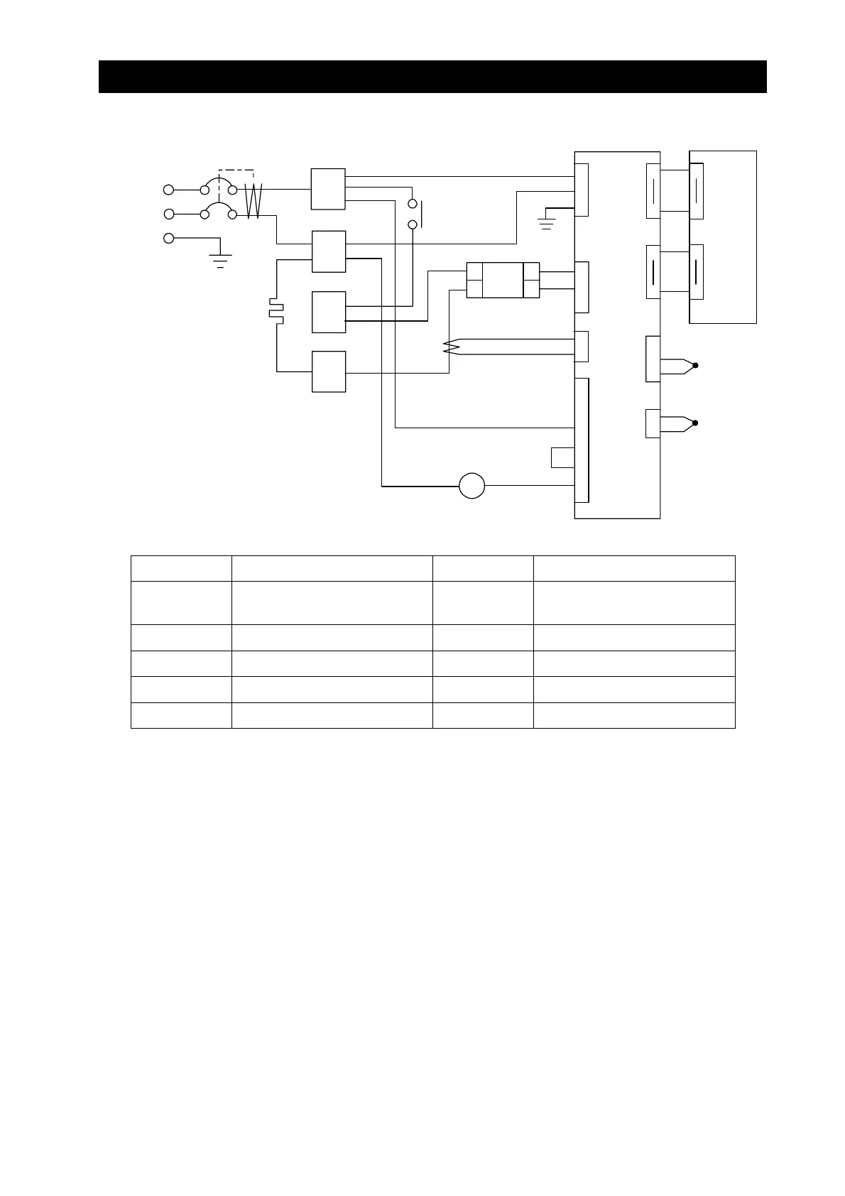
11. Wiring diagram
DVS402/602
1
2
3
4
T
ELB
AC100V
H
X
3
4
1
2
CT
X1
SSR
2
1
1
3
TB1
CN2
CN1
1
2
CONT
3
2
1
TB2
2
+
-
TH2
TH1
+
-
CN8
CN1
1
18
1
18
PIO
CN9
CN2
1
18
1
18
1
2
3
4
CN4
5
6
.
.
.
.
.
.
1
3
CN52
.
.
Symbol Part name Symbol Part name
ELB ELB with an over current
protector
CONT Control circuit board
T Terminal block PIO Display circuit board
H Heater TH1 Control sensor
X Main relay TH2 Overheat prevention sensor
SSR No-contact relay CT Current detection element