Do you have a question about the Yanmar 4TNV84T-Z and is the answer not in the manual?
Warning about premature failure of electronic components if battery cables are incorrectly disconnected during operation.
Guidelines for extending the 60-inch wire harness, emphasizing soldering and sealing.
Connect pin #2 to pin #11 on the Deutsch accessory connector for constant speed.
Connect pin #2 to pin #12 on the Deutsch accessory connector for constant speed.
Guidelines for installing the ECU remotely, focusing on location, ventilation, and connector orientation.
Lay out the harness on the engine to determine fitment and placement of components.
Secure the main harness loom to the flywheel housing using a specific mount and wire tie.
Secure the ECU with connector facing down, creating a downward loop for the harness.
Secure the fuel injection pump harness branch to the block using a P-clamp for routing.
Route EGR branch behind cooling hoses and coolant sensor wire across the valve cover.
Detailed view of component connections, wire gauges, and terminal designations.
Pin assignments for various connectors including ECU, accessory, and CAN interfaces.
Notes on vibration, shock resistance, temperature range, and avoiding dielectric grease on sealed connectors.
Guidance on power connections, battery disconnection before servicing, and avoiding high-pressure washing.
Specifications for relay replacements and instructions for submitting claims to Yanmar.
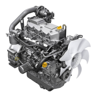
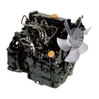
| Engine Model | 4TNV84T-Z |
|---|---|
| Number of Cylinders | 4 |
| Aspiration | Turbocharged |
| Fuel System | Direct injection |
| Cooling System | Water-cooled |
| Engine Type | Vertical, water-cooled, 4-cycle diesel |
| Bore x Stroke | 84 x 90 mm |
| Max Power | 35.4 kW (47.5 hp) @ 2600 rpm |
| Max Torque | 161 Nm / 1600 rpm |
| Starting System | Electric |
| Lubrication System | Forced lubrication |
| Weight | 190 kg |