6.7
Lift Arm Assembly
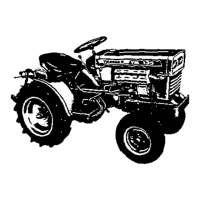
[For
serial No. after 510011
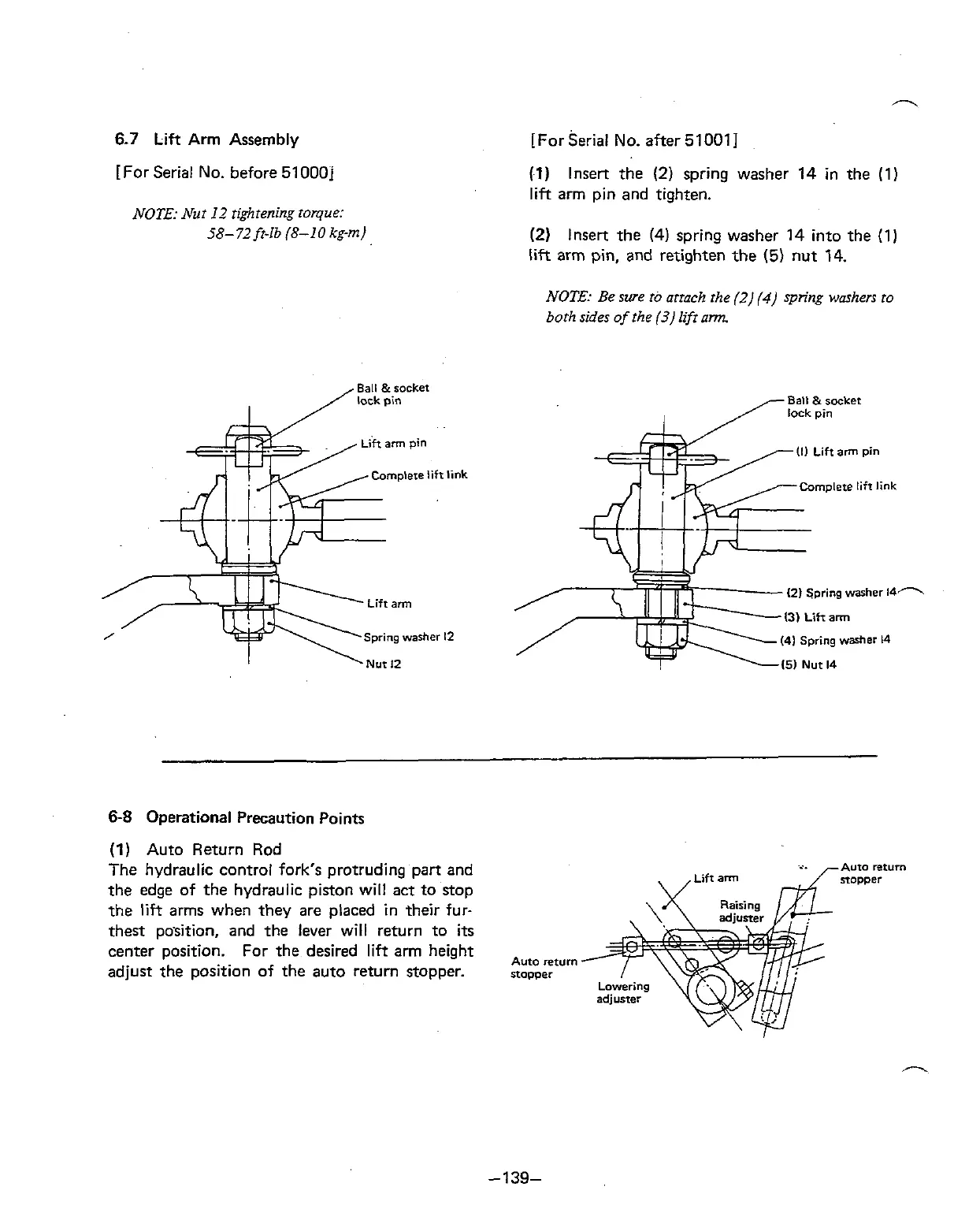
[For Serial No. before 51000j
NOTE: Nut I2 tightening torque:
58-
72
ft-lb (8-1
0
kg-m)
Ball
&rocket
/lock
pin
I
'1)
Insert the
(2)
spring washer 14 in the (1)
lift
arm pin and tighten.
(2)
Insert the (4) spring washer 14 into the (1)
lift arm pin, and retighten the
(5)
nut 14.
NOTE: Be swe
ro
attach the (2)
(4)
spring washers to
both sides of the
(3)
lift
arm
Ball
&rocket
I
/lock
pin
(2)
Spring
washer
14'1
41
Spring
washer
14
68
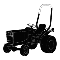
Operational Precaution Points
(1)
Auto Return Rod
The hydraulic control fork's protruding part and
the edge of the hydraulic piston will act to stop
the
lift
arms when they are placed in their fur-
thest position, and the lever will return to
its
center position. For the desired lift arm height
Auto
return
adjust the position of the auto return stopper.
stopper