8
SECTION 8: ASSEMBLY
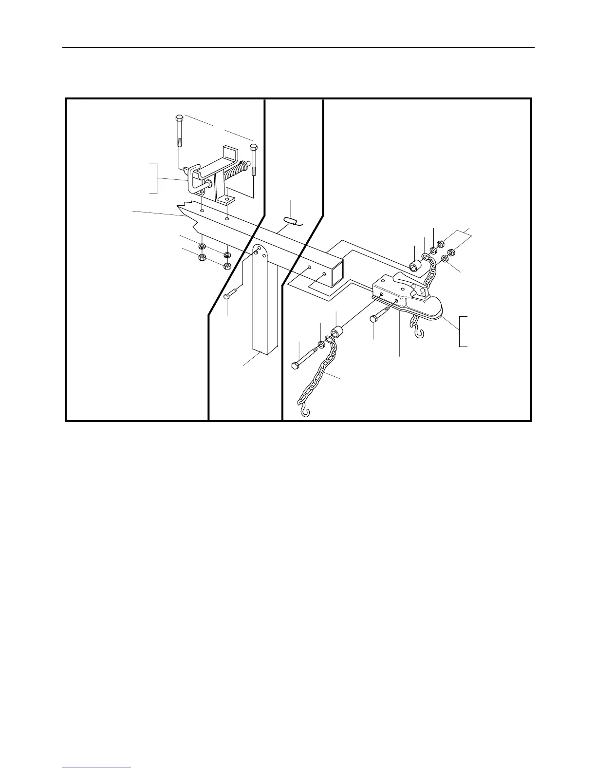
ASSEMBLING THE TONGUE
Figure 2
The hardware that is used to assemble the tongue
will be found in place on the tongue and hitch. The
assembly has been divided into three assemblies A,
B and C. Locate the section of Figure 2 that is
appropriate to the instructions.
ASSEMBLY A (See Figure 2)
Attach the Beam Support - Latch Bracket as follows:
1. Remove two hex bolts (A), lock washers (B)
and hex nuts (C) from the tongue, using two
9/16" wrenches.
2. Place the beam support/latch bracket on the
tongue as shown. Secure with hex bolts (A),
lock washers (B) and hex nuts (C) just
removed. Tighten securely.
ASSEMBLY B (See Figure 2)
Prepare the Jack Stand as follows:
1. The jack stand is in the transport position.
Remove spring pin (E) and clevis pin (D). Pivot
the jack stand to the operating position, and
secure with the clevis pin (D) and spring pin (E).
ASSEMBLY C (See Figure 2)
Attach the hitch as follows:
1. Using two 9/16" wrenches, remove the
hardware (F, G, H, I, J and K) assembled on the
hitch.
2. Place the hitch in position on the end of the
tongue as shown. Insert hex bolt (F) (with H, I
and J attached) through hitch and tongue. Pivot
the first chain link on the hex bolt (F) so it faces
the ball end of hitch.
3. Place other spacer (J), safety chain (I) and flat
washer (H) on hex bolt, with the first link of the
chain also facing the ball end of hitch. Secure
with hex lock nut (G).
4. Secure front of tow hitch to tongue with hex bolt
(K), lock washer (H) and hex nut (G), using the
forward hole in hitch and tongue.
5. Tighten hardware securely using two 9/16"
wrenches.
A
BC
A
B
C
D
E
G
Beam Support
Latch Bracket
Tongue
Jack Stand
Hitch
F
H
I
J
K
H
J
I
Ball End
Of Hitch
H