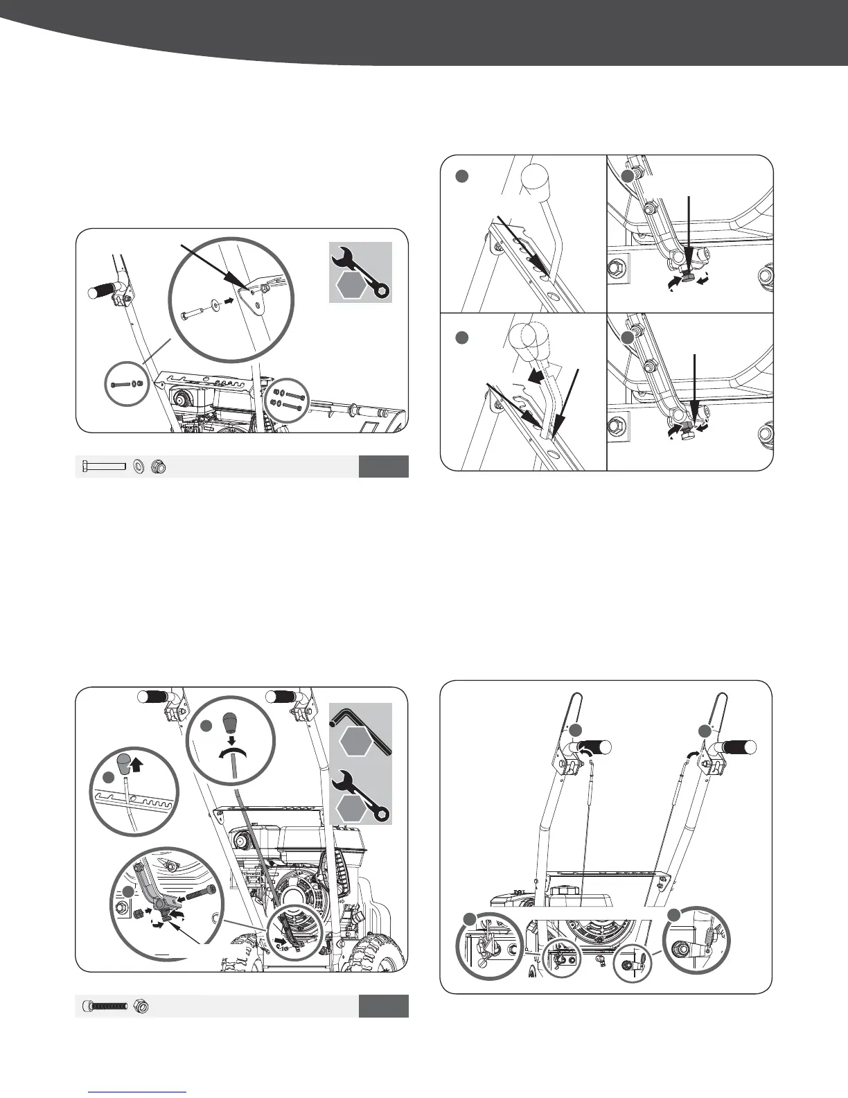
SPEED SHIFT LINKAGE CONTROL CABLES
CONTROL PANEL
1. Remove the knob to slide the shift lever through the slot in the
control panel.
2. The adjusting bolt will need to be loosen to install shift arm
(See Figure 5a #2). Secure shift lever to the shift arm with
screw and nut.
3. Reattach the knob.
4. Slowly tighten the adjusting bolt until the shift lever has
tension with a spring action when shifting from Neutral to a
Drive Gear position.
1. Place the control panel between the handle bars. Slide the
three bolts and washers through the two holes on the right side
RIWKHKDQGOHEDUDQGWKHOHIWXSSHUKROH6HFXUHWKHPE\ĆQJHU
tightening the nuts. Leave the lower hole on the left hand side
without a bolt. This will be used to secure the directional chute
control assembly later. (See Figure 4).
M6 X 40 X 3
2
M6 X 30 X 1
3
10
mm
5
mm
a
b
a
b
10
mm
X 2
21
43
Jam Nut
Adjusting Bolt
Neutral Position
Drive Gear
Position
Neutral
Position
'LVFRQQHFW WKH =ĆWWLQJV IURP WKH WXUQEXFNOHV DQG KRRN WKHP
into the lower holes in the clutch levers. Thread the turnbuckles
ZLWKRXWWXUQLQJWKHFDEOHVRQWR=ĆWWLQJV XQWLO WKHUH LV QR VODFN
LQ WKH FDEOHV 'R QRW RYHUWLJKWHQ WKH FDEOHV +ROG WKH ćDWV RQ
the turnbuckles with pliers and tighten the jam nuts against the
turnbuckles. (See Figure 6b)
2. Once control panel is installed. Securely tighten lower handle
and control panel bolts.
9
|
Assembly
Figure 5a
Figure 4
Figure 6a
Figure 5b