DISCHARGE CHUTE
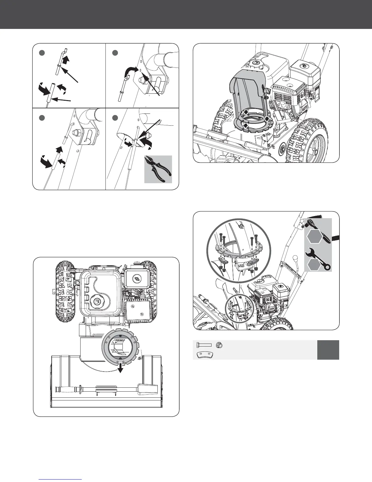
DIRECTIONAL CHUTE CONTROL
6HFXUH WKH WKUHH ćDQJH NHHSHUVWR WKH ERWWRP RI WKH FKXWH
FUDQNćDQJHE\VOLGLQJWKHEROWVWKURXJKWKHFKXWHEDVHKROHV
sliding the keepers up from the bottom, then securing them
with the included nuts. (See Figure 7c)
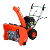
6LWWKHFKXWHFUDQNćDQJHRQWRSRIWKHLPSHOOHUKRXVLQJ0DNH
sure the notched edge is on the left side and the pre-greased
surface is on the bottom. (See Figure 7a)
2. Place the discharge chute facing it forward over the chute
FUDQNćDQJH6HHFigure 7b)
M6 X 30 X 6
4
X 3
10
mm
10 mm
Figure 7c
Figure 7a
Figure 7b
Figure 6b
1. Slide the spiral end of the directional chute control lever into
the chute bracket.
2. Attach the directional chute control lever to the handlebar
through the upper holes on the left handle by sliding the bolt
thru the hole. Use the curved washer and nut to secure it to
WKHKDQGOHEDU/HDYHLWĆQJHUWLJKWIRUHDVLHUDOLJQPHQWODWHU
6HFXUHWKHVSLUDOHQGRQWKHFKXWHEUDFNHWE\VOLGLQJRQWKHćDW
washer and clevis pin. (See Figure 8a)
Lower Hole
Turnbuckle
=ĆWWLQJ
-DP1XW
1 2
3 4
10
Two-Stage Snow Blower
»
Operator’s Manual
Assembly
|