PLOW BLADE (OPTIONAL)
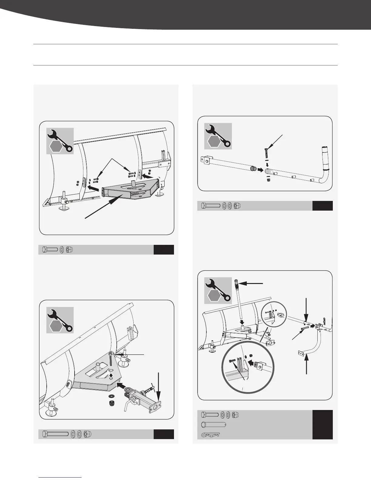
Figure 2a
Figure 2b
Figure 2c
Figure 2d
1. Mount the mounting bracket to the blade using M8×30
hex bolts, washers and nuts. (See Figure 2a)
3. Insert the shorter control lever into the longer lever. Align
holes and fasten with M8×40 hex bolt, washers and nut.
(See Figure 2c)
4. Attach control lever to the guide tube. Line up holes and
fasten with M8×35 bolt, washers and nut.
5. Insert the handle grip into the holder.
6. Secure the support bracket into the control lever with pin
10×60 and bridge clip. (See Figure 2d)
2. Position the pivot bracket inside the mounting bracket and
align with mounting bracket holes. Secure with M20×95
hex bolt, washers and nut. (See Figure 2b)
M8 × 30 × 4
1
M8 × 40 × 1
3
M20 × 95 × 1
2
M8×30 (×4)
Mounting Bracket
Support Bracket
Control Lever
Handle Grip
M8×35 (×1)
10×60 (×1)
M8×40 (×1)
M8 × 35 × 1
4
10 × 60 × 1
2 × 11 × 35 × 1
13
mm
× 2
13
mm
× 2
13
mm
× 2
ASSEMBLY OF OPTIONAL ACCESSORIES
This trackbarrow was completely assembled at the factory. To assemble the optional plow blade follow the below instructions.
30
mm
× 2
9
YD8105PM04 - 1804
|
Assembly of Optional Accessories