- 11 -
Nominal voltage
Current
Tension
Cutting speed
No Load Speed
Cutting length
Oil tank capacity Max
Item No. 2391574(EGTACPS001)
120V/60HZ
8A
SDS
36 f/s
6200 RPM
10”
75ml
*) The specied values are emission values and do not necessarily represent safe workplace values. Al-
though there is a correlation between emission and immission levels, this cannot be used to infer wheth-
er additional safety measures are necessary or not. Factors which aect the current immission levels at
the workplace, include the type of room, other sources of noise, e. g. the number of machines operating
and other processes taking place in the vicinity. Permitted workplace values can dier from country to
country. This information is designed to help the user to better assess the dangers and risks.
**) The specied vibration emission value was measured in accordance with a normed test procedure and
can be used in order to compare one tool with another. The specied vibration emission value can also
be used for an introductory evaluation of the exposure. The vibration emission value may uctuate from
the specied value during actual use of the power tool. These uctuations will depend on the way in
which the power tool is used. Try to keep vibrations to a minimum. One method of reducing the vibra-
tion load is, for example, limiting the length of time you work with the tool. All parts of the operating cycle
must be taken into account for this purpose (for example, also including times in which the power tool is
switched o and times in which it is switched on, but is running without load).
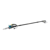
ASSEMBLY OF THE MACHINE
1. Open the box and nd the below
three parts as shown on Page 7:
-- Cutting Head x 1
-- Pole Assembly x 1
-- Handle x 1
-- Hex Key x 1
-- Instruction Manual x 1
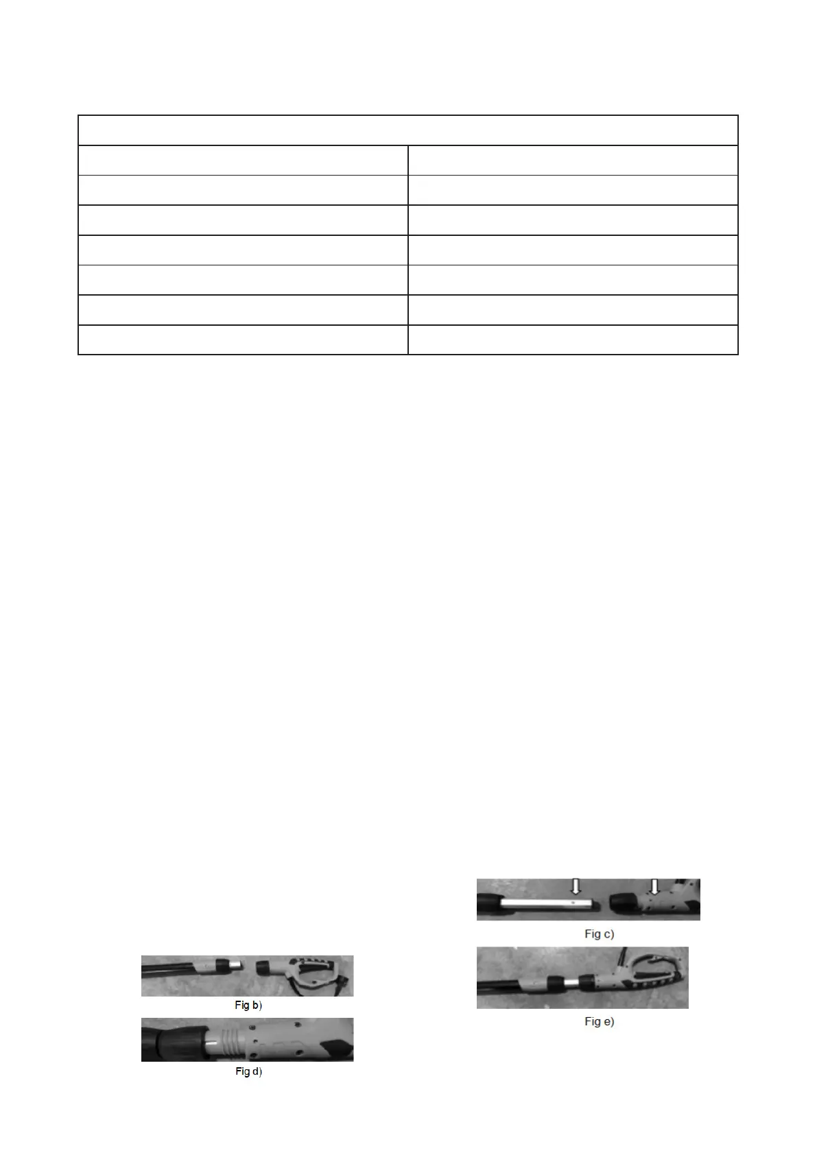
2. Assembly of the handle and Pole
a. Take out the Pole Assembly and the Handle
b. Unscrew the Shaft Coupling 3(3) by anti-clock-
wise direction and pull out the Extension Pole 4
until the desired length and screw by
clockwise to lock the Shaft Coupling 3(3).
NOTE:
the extended pole 4 should be longer than
15cm.
c. Unscrew the Shaft Coupling 3(4) by anti-clock-
wise direction on Handle. Make the pin on Alumi-
num Pole align with the hole on the handle for
next step.
d. Plug the extended Aluminum Pole into the han-
dle. Now the pin has been locked in the hole of
handle and handle won’t come o.
e. Screw tighten the shaft coupling 3(4) by clock-
wise direction. At this step, the connection be-
tween handle and pole is nished.