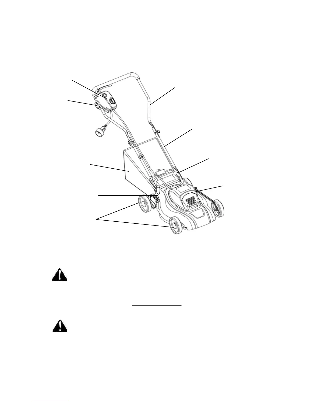
DESCRIPTION OF PARTS
Fig. 2
Up
per handle
Power switch
assembl
y
Cord restraint
Middle handle
Lower handle
Rear bag
Motor
ho
using
Height adjustment
lever
Whe
e
l
Switch Assembly
Read this Owner's Manual and safety rules before operating the lawn mower. Compare the illustration in Fig. 2
to the lawn mower in order to become familiar with the location of the various controls and adjustments.
Save this manual for future reference
.
WARNING: The operation of any mower can result in foreign objects being thrown into the eyes,
which can cause severe eye damage. Always wear safety glasses while operating the mower and
while performing any adjustments or repairs
.
The switch assembly is located on the upper handle of the mower. The switch starts and stops the motor
and the blade.
WARNING: The switch assembly is a safety device. Do not attempt to bypass its operation
.
Rear Trailing Shield
The rear trailing shield, which is attached between the rear wheels of the mower, is designed to minimize the
possibility of objects being thrown at the operator from the rear of the mower
.

 Loading...