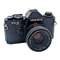
The device described in this manual is the Yashica FX-D Quartz camera, a single-lens reflex (SLR) camera with quartz-controlled features, designed for both automatic and manual exposure control. This repair manual provides detailed instructions for dismantling, adjusting, and troubleshooting the camera, offering insights into its construction and operational principles.
Function Description:
The FX-D Quartz is a sophisticated camera featuring a quartz-controlled shutter system, offering precise exposure timing. It supports both auto-exposure (AE) and manual exposure modes, catering to a range of photographic needs. A key feature is its S-LED (Shutter speed LED) display in the viewfinder, which provides critical exposure information to the user. This includes indications for "OVER" and "UNDER" exposure, as well as flash-ready status and battery check. The camera incorporates an Aperture Variable Resistor (AVR) for aperture control and an ASA dial for film speed settings, which are crucial for accurate exposure calculations. The camera also includes a self-timer function, indicated by a blinking LED and an audible beep.
Important Technical Specifications:
- Shutter Speed Control: Quartz-controlled, offering precise timing for various shutter speeds. The manual lists standard shutter speeds from 1/1000 sec down to 2 sec, plus "B" (Bulb) and "X" (flash synchronization).
- Auto-Exposure (AE): The auto-exposure system is designed for use with a standard lens, setting the aperture at F5.6 with AUTO and ASA80. The E.E. camera tester is used at ASA100, K=1.3 for measurement. EV tolerance for auto-exposure is typically ±0.7 EV, with some variations up to ±0.8 EV for specific settings.
- Shutter Curtain Speed: The shutter curtain speed should be within 6.0 ms.
- Flash Synchronization (Synchro Contact):
- Synchronizer delay time: 0.3 to 0.9 ms (checked at "X" position with a shutter tester).
- Synchro contact efficiency: 65% or more (TIME INT. 1 ms).
- Synchro insulation resistance: 30MΩ or more (DC500V).
- Voltage Dependence: The camera operates within a voltage range of 2.75V to 3.2V DC.
- Battery Check Display: A 16-dot LED indicates battery status. At 2.45V, a 1Hz blinking alarm is triggered.
- Self-timer: Quartz-controlled 10-second delayed exposure. The LED blinks with an audible tone (beep) signal at 4Hz for the first 8 seconds, then at 4Hz for the last two seconds before the shutter trips.
- Flash Unit Compatibility: Specifically designed for use with the CS-201 Auto Flash unit, which has a guide number of 20.
- Circuitry: Features a CPU Digital LSI and an Analog IC, along with a 32.768 KHz Quartz Oscillator for timing.
Usage Features:
- Viewfinder Display: The S-LED display in the viewfinder provides comprehensive information, including shutter speed, flash-ready status, and battery check. It indicates "OVER" and "UNDER" exposure conditions through blinking LEDs and an audible beep tone.
- Exposure Modes: Supports both AUTO and Manual exposure modes. In AUTO mode, the camera automatically selects the appropriate shutter speed. In Manual mode, the user sets the shutter speed, and the LED display helps in adjusting for correct exposure.
- AE Lock: The AE Lock function allows the user to lock the exposure settings, enabling recomposition without changing the exposure. The viewfinder LEDs light up for 10 seconds after the AE Lock lever is released.
- Flash Indication: When a compatible flash unit (CS201 AUTO, TLA20, TLA30) is fully charged, a flash mark (✓) is lit in the viewfinder.
- Self-timer: A 10-second self-timer with visual and audible cues (blinking LED and beep) is integrated for delayed shutter release.
Maintenance Features:
The manual is primarily a repair guide, offering detailed procedures for maintenance and troubleshooting:
- Dismantling Procedures: Step-by-step instructions for removing outside covers (bottom, top, leathers, mount cover sub ass'y), the mirror box ass'y, shutter base plate ass'y, and winding base plate ass'y. This includes unsoldering lead wires from the flexible printed circuit (FPC) at various points.
- Adjustment Procedures:
- AVR Base Plate Adjustment: Setting the F. stop connecting ring and AVR gear to their correct start positions.
- Mirror Position and Finder Focus Adjustment: Includes horizontal and 45° adjustment of the mirror, and upward/downward location for fine finder focus. Rough focus adjustment is done by exchanging washers under the pentagonal framework. Seven types of adjusting washers (0.05 to 0.7 mm) are available.
- Anti-rewind Claw Adjustment: Ensuring the anti-rewind claw is released when the A-gear stopper is engaged.
- TF-switch Adjustment: Ensuring the shutter actuates correctly at a specific position of the MD cap ring.
- S-LED Position Adjustment: Adjusting the S-LEDs in the viewfinder to ensure all indicators ("B" to "OVER" and "✓") are normally seen. This involves loosening screws and shifting the adjusting plate, with screws to be locked with glue after adjustment.
- Voltage Check and Adjustment: Detailed instructions for checking and adjusting various voltages (OFF-SET, Standard, Auto-Exposure, Battery Check) using a digital multimeter, under specific conditions (ASA 100, no lens, 2.8V DC power, exposure check button pressed).
- Amplifier Replacement Procedure: Outlines the steps for replacing the amplifier, including unsoldering 13 lead wires and removing various setscrews.
- Malfunction and Causes: A comprehensive troubleshooting guide that lists common malfunctions (shutter not operating, incorrect auto-exposure, wrong LED indications, no beep, defective self-timer, battery warning issues) and their potential causes, directing the technician to specific components (e.g., F.P.C., Amplifier, various resistors, transistors, switches, and contacts).
The manual emphasizes careful handling during disassembly and assembly, particularly for delicate components like the counter G-1 and the release magnet. It also highlights the reusability of self-stick leathers with additional adhesive if needed.