Diagnostics 3-10
# Network Termination
Determine the topology of the network. In a BUS topology, there is a definite beginning and end to the network. In a Free topology only the
either the beginning of end of the network can be determined. Refer to the diagrams below for examples of BUS and Free topologies.
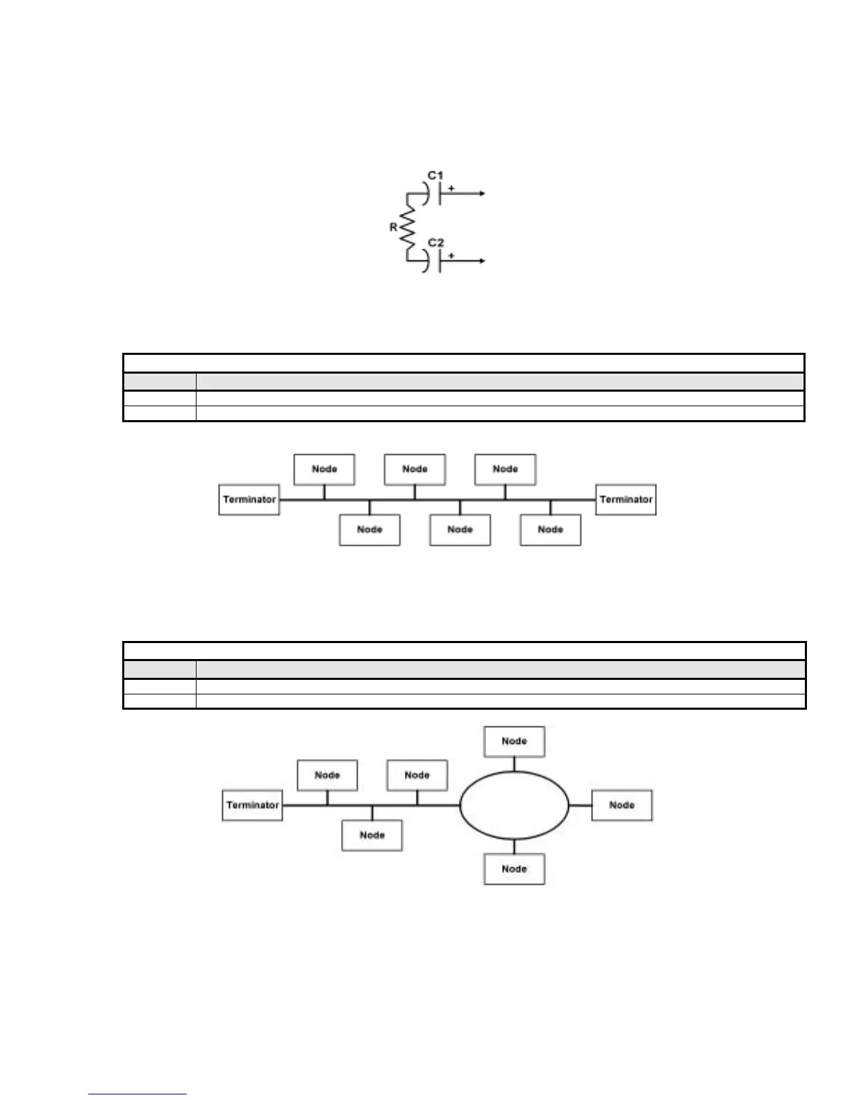
Network termination consists of a resistor and two capacitors as shown in the figure below. Note the polarity of the capacitors. Refer to the “FT
3120/FT3150 Smart Transceiver Data Book” for more information on network termination. It be downloaded from www.echelon.com.
Figure 3.5 – L
ONWORKS NetworkTermination
! BUS topology
BUS topology requires termination resistors at the beginning and end of the network.
Table 3.5 – BUS Topology Terminator Device Values
Device Description
R
105Ω, 1%, ⅛W
C1 and C2
100µF, ≥50V (typically aluminum-electrolytic)
Figure 3.6 – L
ONWORKS BUS Network Topology
! Free topology
Free topology network requires only one terminator.
Table 3.6 - Free Topology Terminator Device Values
Device Description
R
52.3Ω, 1%, ⅛W
C1 and C2
100µF, ≥50V (typically aluminum-electrolytic)
Figure 3.7 – L
ONWORKS Free Network Topology