Diagnostics 3-9
Cables and Wiring
Standard network wiring practices should be followed.
! Do not route any network wires close to high voltage or high current wires. It is recommended that network wiring be in its own
conduit or trough. It may, however, be routed with low voltage DC wires.
! If the network must cross high voltage or current wires, the network must cross perpendicular to the high voltage or current wires.
! If a clean, noise free ground cannot be found locally to the device, route a ground wire of sufficient size to each device. Remember to
provide a single point ground to avoid ground loops.
! Follow all local electrical codes.
# Network Cables
Choose the correct cable for the application and network configuration. For more information on cables and cabling refer to “Junction Box and
Wiring Guidelines for Twisted Pair L
ONWORKS Networks” Echelon engineering bulletin #005-0023-01. It may be downloaded from
www.echelon.com.
Table 3.3 BUS Topology Specifications
Cable Maximum bus length(Meters)
Belden 85102 2700
Belden 8471 2700
Level IV, 22AWG 1400
JY(St) Y 2x2x0.8 900
TIA Category 5 900
Note: A doubly-terminated bus may have stubs of up to 3 meters from the bus to each device.
Table 3.4 Free Topology Specifications
Cable Maximum device-to-device distance (Meters) Maximum total Wire length(Meters)
Belden 85102 500 500
Belden 8471 400 500
Level IV, 22AWG 400 500
JY(St) Y 2x2x0.8 320 500
TIA Category 5 250 450
# Shield Grounds
Shields can be a prime source of noise in any network. The general rule is to ground the shield at the signal source. Depending on the type of
noise and the quality of the ground plane, it may be advisable to ground the shield at each device and/or at both ends of the network segment. If
there is noise on the network or intermittent short term communication failures, removing the shield from the device connection is usually one
of the first methods used restore communications stability. Also, if there is a disparity in the ground planes between devices, it is preferable to
disconnect the shield from the device connection. The shield must still remain contiguous even if removed from a device connector.
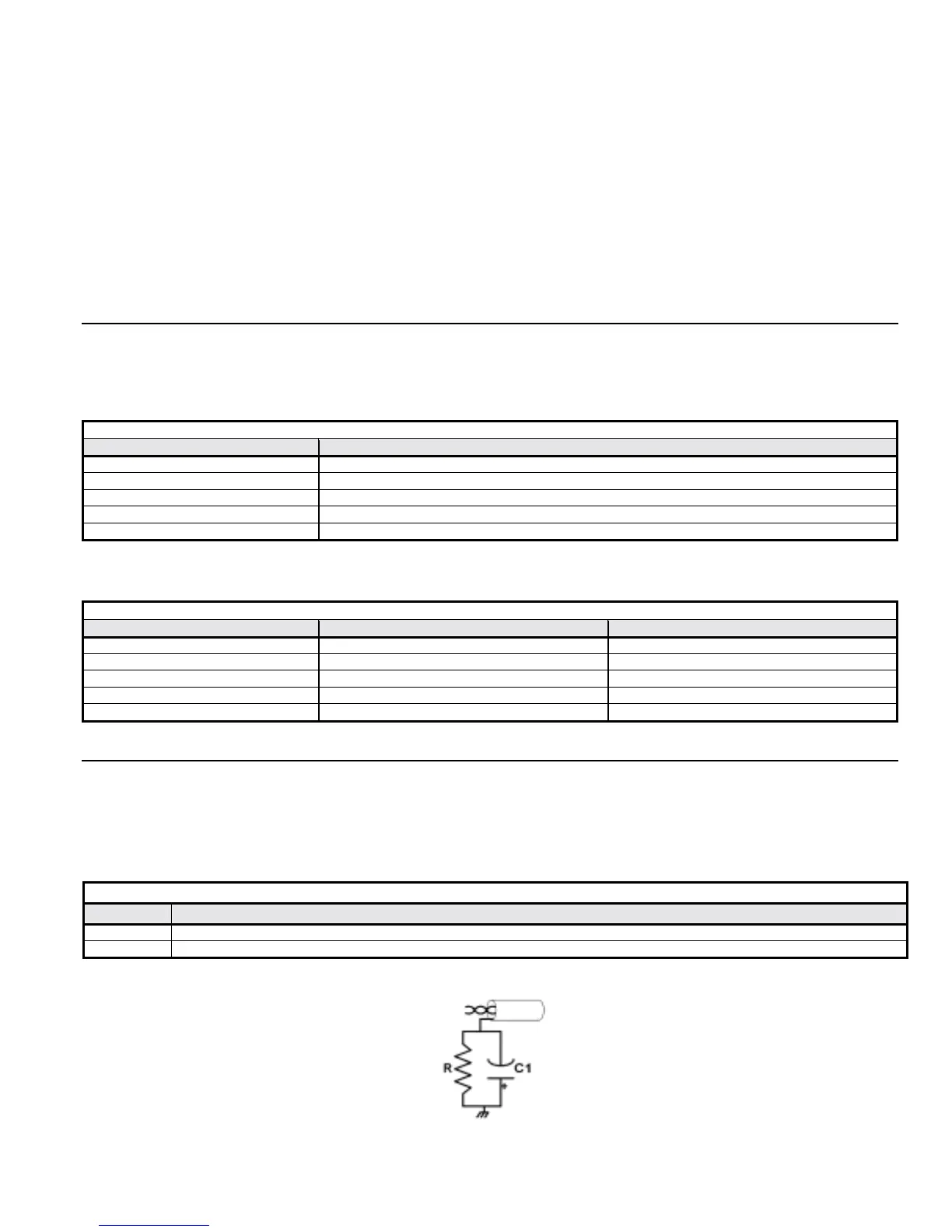
Table 3.5 – Shield Gournd
Device Description
R
470kΩ, 5%, ¼W
C1
0.1µF, 10%, Metalized polyester, ≥100V
Figure 3.4 – L
ONWORKS Shield ground