Description
of digital operator
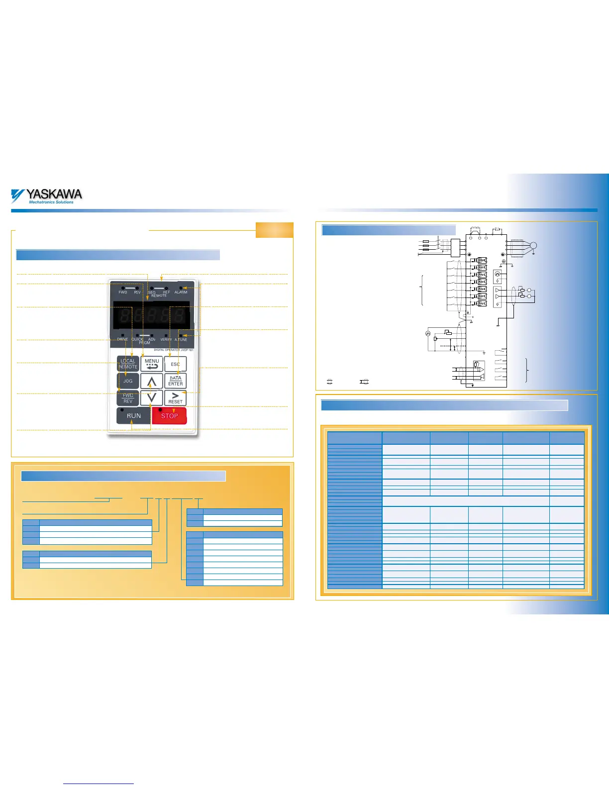
Overview of display and keypad
Overview of display and keypad
Varispeed F7
Varispeed F7
Data display
Menu button
Switches menu within
the hierarchy.
Local/Remote button
Changes over from control
with the digital operator to
control via the terminal block.
JOG button
Enables RUN with JOG speed,
which has highest priority.
FWD/REV button
Reverses the direction of
rotation of the motor.
Arrow up
button
Increases the parameter
number or data value.
Arrow down
button
Decreases the parameter
number or data value.
Digital operator
Status LEDs
One of these comes on to indicate
the inverter status.
ESC button
Returns to previous menu in the
hierarchy without saving.
Enter button
Saves parameter setting data.
Entering a parameter number in the
PRGM mode displays the associat-
ed data.
Reset button
Shifts the digit of a value that is
selected to be changed resets
operation when a fault has occured
(ecknowledgement)
Stop button
Stops the motor.
Run button
Starts the motor. The LED in the
top left corner of the button lights
up on to indicate that the motor is
running.
CIMR – F7C40P41
Inverter
Varispeed F7 series
No. Rated output of motor
0P4 0.55 kW
4P0 4.0 kW
7P5 7.5 kW
011 11 kW
045 45 kW
110 110 kW
160 160 kW
300 300 kW
Code Power supply
2 three phase 200V AC
4
three phase 400V AC
Code Protection
0 IP00
1 NEMA1/IP20
Specification/Nameplate
Specification/Nameplate
Code Specification
A
Japanese standard
C
European standard
U American standard
The radio interference filters tested by Yaskawa are listed below. The stipulations of the Operating Manual (YEG-TOE-S616-55.1) or
separate EMC documentation relating to their connection must be followed to achieve proper electromagnetic compatibility (EMC).
Radio interference suppression filters for conformity with the EMC Directive (CE)
Radio interference suppression filters for conformity with the EMC Directive (CE)
DC reactor (optional)
Braking resistor unit (optional)
+ 1 + 2
–
B1 B2
S1
S2
S3
S4
S5
S6
S7
SN
U/T1
V/T2
W/T3
M
shielded cable
shielded twisted pair cable
MP
AC
Pulse train output
AM
FM
AC
AM
FM
20kΩ
20kΩ
Current display
Multi-functional analog output 1
Multi-functional analog output 2
(-10 to +10V 2mA/4 to 20mA)
E(G)
MA
MB
MC
M1
M2
M3
M4
M5
M6
Fault contact output
During Run
Zero speed
Frequency
agree 1
Multi-functional output digital output
(250V AC, 1A 30V DC,1A)
0V
-V -15V 20mA
R+
R-
S+
S-
IG
Memobus communication
RS-485/422
2kΩ
2kΩ
+V -15V 20mA
A1 Analog input 1
A2 Analog input 2
AC
-10…+10V
4…20mA
RP Puls train input
E(G)
+24V
R/L1
S/L2
T/L3
Forward Run/Stop
Reverse Run/Stop
External fault
Fault reset
Multi-step speed
setting 1
Multi-step speed
setting 2
Jog frequency
selection
Multi-functional digital
inputs
SC
SP
Standard connection diagram for Varispeed F7
Standard connection diagram for Varispeed F7
Dimensions
WxHxD (mm)
Current
(A)
Weight
(kg)
Inverter model Filter model
Fit under
yes/no
CIMR-F7C20P4
CIMR-F7C20P7 FS 5972-10-07 10 1.1 141x330x46 yes
CIMR-F7C21P5
CIMR-F7C22P2 FS 5972-18-07 18 1.3 141x330x46 yes
CIMR-F7C23P7
CIMR-F7C25P5
FS 5973-35-07 35 1.4 141x330x46 yes
CIMR-F7C27P5 FS 5973-60-07 60 3 206x355x60 yes
CIMR-F7C2011
CIMR-F7C2015 FS 5973-100-07 100 4.9 236x408x80 yes
CIMR-F7C2018
CIMR-F7C2022
CIMR-F7C2030
FS 5973-130-35 130 4.3 90x366x180 no
CIMR-F7C2037 FS 5973-160-40 160 6 120x451x170 no
CIMR-F7C2045
FS 5973-240-37 240 11 130x610x240 no
CIMR-F7C2055
CIMR-F7C2075
CIMR-F7C2090 Filters under development no
CIMR-F7C2110
CIMR-F7C40P4
CIMR-F7C40P7
CIMR-F7C41P5 FS 5972-10-07 10 1.1 141x330x46 yes
CIMR-F7C42P2
CIMR-F7C43P7
CIMR-F7C44P0
CIMR-F7C45P5
FS 5972-18-07 18 1.3 141x330x46 yes
CIMR-F7C47P5 FS 5972-21-07 21 1.8 206x355x50 yes
CIMR-F7C4011 FS 5972-35-07 35 2.1 206x355x50 yes
CIMR-F7C4015
CIMR-F7C4018
FS 5972-60-07 60 4 236x408x65 yes
CIMR-F7C4022
CIMR-F7C4030
FS 5972-70-52 70 3.4 80x329x185 no
CIMR-F7C4037
CIMR-F7C4045
FS 5972-100-35 100 4.5 90x326x150 no
CIMR-F7C4055 FS 5972-130-35 130 4.7 90x366x180 no
CIMR-F7C4075 FS 5972-170-40 170 6 120x451x170 no
CIMR-F7C4090 FS 5972-250-37 or 250 11.7 130x610x240 no
CIMR-F7C4110 FS 3359-250-28 250 7.0 230x300x125 no
CIMR-F7C4132 FS 5972-400-99 or 400 18.5 300x610x160 no
CIMR-F7C4160 FS 5972-410-99 410 10.5 260x386x115 no
CIMR-F7C4185 FS 5972-410-99 410 10.5 260x386x115 no
CIMR-F7C4220 FS 5972-600-99 600 11 260x386x135 no
CIMR-F7C4300 FS 5972-800-99 800 31 300x716x160 no
Line
Filter
Main contactor
Fuse
L1
L2
L3
PE
3-phase power supply
380 to 480 V
50/60 Hz

 Loading...


