Figure
2
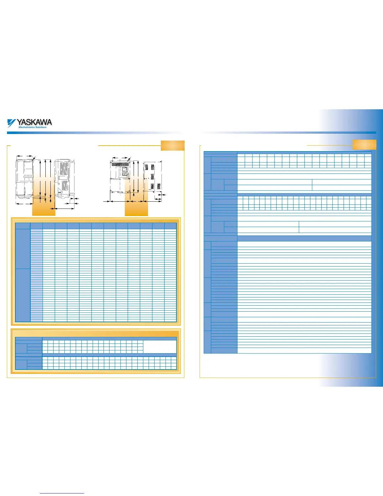
Dimensions:
(IP20 protection) (IP00 protection)
Figure 1
Standard specifications
*1: The recommended maximum connected load is specified for a four pole standard motor. Choose the version of the inverter that does not exceed
the rated current of the motor.
T
3
B 1
4-d
B
H 1
H 2
H 0
H 3
H
4
T 1
t1
B1
H 1
H
H2
t1
4-d
B T(5) (5)(5)
T1
Varispeed F7
Varispeed F7
Varispeed F7
Varispeed F7
Voltage class
Inverter model CIMR-F7C
Recommended maximum
motor output (kW) *1
Rated output (kVA)
Rated current (A)
Max. output voltage
Max. output frequency
Rated input voltage and
frequency
Suppression
of harmonic
distorsion
DC bus
reactor
Double diode
12 pulse supply
Inverter
output
Mains input
200 V
20P4 20P7 21P5 22P2 23P7 25P5 27P5 2011 2015 2018 2022 2030 2037 2045 2055 2075 2090 2110
0.55 0.75 1.5 2.2 3.7 5.5 7.5 11 15 18.5 22 30 37 45 55 75 90 110
1.2 1.6 2.7 3.7 5.7 8.8 12 17 22 27 32 44 55 69 82 110 130 160
3.2 4.1 7 9.6 15 23 31 45 58 71 85 115 145 180 215 283 346 415
three phase 200 to 240V (proportional to input voltage)
150Hz in constant torque mode, 400Hz in variable torque mode
three phase, 200 to 240V, 50/60Hz
Optional Built in
not available Standard
Voltage class
Inverter model CIMR-F7C
Recommended maximum
motor output (kW) *1
Rated output (kVA)
Rated current (A)
Max. output voltage
Max. output frequency
Rated input voltage and
frequency
Suppression
of harmonic
distorsion
DC bus
reactor
Double diode
12 pulse supply
Inverter
output
Mains input
400 V
40P4 40P7 41P5 42P2 43P7 44P0 45P5 47P5 4011 4015 4018 4022 4030 4037 4045 4055 4075 4090 4110 4132 4160 4185 4220 4300
0.55 0.75 1.5 2.2 3.7 4 5.5 7.5 11 15 18.5 22 30 37 45 55 75 90 110 132 160 185 220 300
1.4 1.6 2.8 4 5.8 6.6 9.5 13 18 24 30 34 46 57 69 85 110 140 160 200 230 280 390 510
1.8 2.1 3.7 5.3 7.6 8.7 12.5 17 24 31 39 45 60 75 91 112 150 180 216 260 304 370 506 675
three phase 380 to 480V (proportional to input voltage)
150Hz in constant torque mode, 400Hz in variable torque mode
three phase, 380 to 480V, 50/60Hz
Optional Built in
not available Standard
General specifications
from -15 to +10%
from -5 to +5%
Sinusoidal pulse width modulation (open loop current vector control, V/f control,V/f control with pulse generator)
1:100 (open loop vector control)
±0.2% (25 ±10°C) (open loop vector control)
Digital reference: 0.01Hz, analog reference: 0.025/50Hz (11-bit plus sign)
0.01 Hz
4 to 20mA (250Ω), -10 to +10V (20kΩ),pulse train input
0.01 to 6000 seconds (4 different independent acceleration and deceleration times)
about 20% without braking resistor, about 125% with braking resistor,(braking chopper built in up to and including 18.5kW)
Fully user-definable
Electronic thermal overload relay (PTC evalution possible)
150% of inverter ratet current for 1 min. in heavy duty mode,120% of inverters rated current for 1 min in normal duty mode
Fault tripping occurs if the DC bus voltage exceeds 410V with a 200V, or 820V with a 400V inverter
Fault tripping occurs if the DC bus voltage drops to a value less than 190V at 200V inverters,or 380V at 400V inverters
Operation can be continuet if the power supply is restored within 2 sec
Controlled by thermistor
Stall prevention during acceleration and deceleration, and operation can be set separately
Protection provided by electronic circuit
The charging indicator lights up if the DC bus circuit voltage exceeds 50V
Seven inputs, of which 5 are fully user-definable with 48 different functions
1 change over contact for fault/ready signal; 3 NO contacts fully user-definable with 35 different functions
1 analog input -10V to +10V, 1 analog input -10V to +10V or 4 to 20 mA, 1 pulse train input,user defibable
2 analog outputs –10 to +10V, switchable to 4 to 20mA with 22 different functions,
1 user-definable pulse train output
5-character, 7-segment display,12 LED status indicators for forwards/reverse, local/remote control, alarm, ready, status of short menu,
standard menu, modified parameters,autotuning, start, stop.
9 buttons for displaying and programming the parameters and changing the speed, RUN button and STOP button
Copy and verify function included
An LCD digital operator with plain text in 7 languages and the same functions as the LED operator is available as an option
IP20 up to and including 18.5kW, IP00 (IP20 optional) from 22kW
Maximum of 95% (non-condensing)
IP20 inverters from -10 to +40°C, IP00 from -10 to +45°C
From -20 to +60°C (short-term in transit)
Indoors (rooms free from corrosive gases and dust)
Maximum of 1000m
Maximum of 9.8m/s
2
(1g) from 10 to 20Hz, maximum of 2m/s
2
(0.2g) from 20 to 50Hz
Allowable mains
voltage fluctuation
Allowable mains frequ. fluct.
Control method
Speed control range
Frequency accuracy
Resolution of
frequency setting
Output frequency resolution
Reference frequency signal
Acceleration/deceleration time
Braking torque
V/f characteristic
Motor protection
Overload
Overvoltage
Undervoltage
momentary power loss
Overheating of heat sink
Stall prevention limit
Earth fault
DC bus charging indication
Digital inputs
Digital outputs
Analog inputs
Analog outputs
Displays
Buttons
Copying function
Option
Case
Relative humidity
Ambient temperature
Storage temperature
Installation location
Height of installation location
Vibration
MainsControl/regulationProtective functions
Inputs and
outputs
Digital operator
Ambient conditions
Dimensions in mm
Heat loss
Voltage
class
Model:
CIMR F7C
BHTB1H1H2D1t1d
Weight
in kg
Fig No
20P4 140 280 157 126 266 7 39 5 M5 3 1
20P7 140 280 157 126 266 7 39 5 M5 3 1
21P5 140 280 157 126 266 7 39 5 M5 3 1
22P2 140 280 157 126 266 7 39 5 M5 3 1
23P7 140 280 177 126 266 7 59 5 M5 4 1
25P5 140 280 177 126 266 7 59 5 M5 4 1
27P5 200 300 197 186 285 7.5 65.5 2.3 M6 6 1
2011 200 300 197 186 285 7.5 65.5 2.3 M6 7 1
2015 240 350 207 216 335 7.5 78 2.3 M6 11 1
2018 240 350 207 216 335 7.5 78 2.3 M6 11 1
2022 250 400 258 195 385 7.5 100 2.3 M6 21 2
2030 275 450 258 220 435 7.5 100 2.3 M6 24 2
2037 375 600 300 250 575 13 100 3.2 M10 57 2
2045 375 600 330 250 575 13 130 3.2 M10 63 2
2055 450 725 350 325 700 13 130 3.2 M10 86 2
2075 450 725 350 325 700 13 130 3.2 M10 87 2
2090 500 850 360 370 820 15 130 4.5 M12 108 2
2110 575 885 380 445 855 15 140 4.5 M12 150 2
40P4 140 280 157 126 266 7 39 5 M5 3 1
40P7 140 280 157 126 266 7 39 5 M5 3 1
41P5 140 280 157 126 266 7 39 5 M5 3 1
42P2 140 280 177 126 266 7 59 5 M5 4 1
43P7 140 280 177 126 266 7 59 5 M5 4 1
44P0 140 280 177 126 266 7 59 5 M5 4 1
45P5 140 280 177 126 266 7 59 5 M5 4 1
47P5 200 300 197 186 285 7.5 65.5 2.3 M6 6 1
4011 200 300 197 186 285 7.5 65.5 2.3 M6 6 1
4015 240 350 207 216 335 7.5 78 2.3 M6 10 1
4018 240 350 207 216 335 7.5 78 2.3 M6 10 1
4022 275 450 258 220 435 7.5 100 2.3 M6 21 2
4030 275 450 258 220 435 7.5 100 2.3 M6 21 2
4037 325 550 283 260 535 7.5 105 2.3 M6 36 2
4045 325 550 283 260 535 7.5 105 2.3 M6 36 2
4055 325 550 283 260 535 7.5 105 2.3 M6 36 2
4075 450 725 350 325 700 13 130 3.2 M10 88 2
4090 450 725 350 325 700 13 130 3.2 M10 89 2
4110 500 850 360 370 820 15 130 4.5 M12 102 2
4132 500 850 360 370 820 15 130 4.5 M12 120 2
4160 575 925 380 445 895 15 140 4.5 M12 160 2
4185 710 1305 415 540 1270 15 125,5 4.5 M12 160 2
4220 710 1305 415 540 1270 15 125,5 4.5 M12 160 2
4300 916 1475 416 730 1440 15 125,5 4.5 M12 160 2
200 V
400 V
Voltage class
Model: CIMR-E7C
Heat sink
Heat loss
in W
Interior
Total
Voltage class
Model: CIMR-E7C
Heat sink
Heat loss
in W
Interior
Total
200 V
400 V
20P4 20P7 21P5 22P2 23P7 25P5 27P5 2011 2015 2018 2022 2030 2037 2045 2055 2075 2090 2110
20 27 50 70 112 164 219 374 429 501 586 865 1015 1266 1588 2019 2437 2733
39 42 50 59 74 84 113 170 183 211 274 352 411 505 619 838 997 1242
59 69 100 129 186 248 332 544 612 712 860 1217 1426 1771 2207 2857 3434 3975
40P4 40P7 41P5 42P2 43P7 44P0 45P5 47P5 4011 4015 4018 4022 4030 4037 4045 4055 4075 4090 4110 4132 4160 4185 4220 4300
14 17 36 59 80 91 127 193 252 326 426 466 678 784 901 1203 1399 1614 2097 2388 2791 3237 3740 5838
39 41 48 56 68 70 82 114 158 172 208 259 317 360 415 495 575 671 853 1002 1147 1372 1537 2320
53 58 84 115 148 161 209 307 410 498 634 725 995 1144 1316 1698 1974 2285 2950 3390 3938 4609 5277 8158

 Loading...


