84
• Building Interface Circuits with External Devices
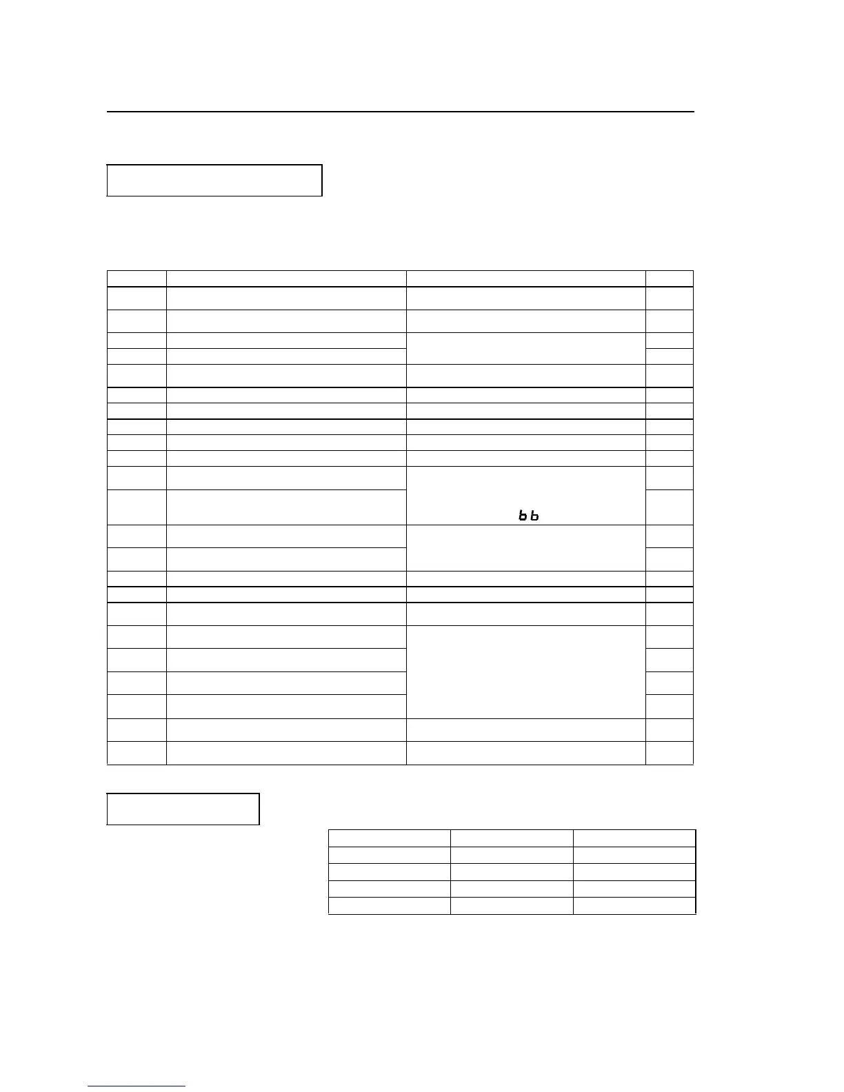
Multi-function input terminal S2 to S5 functions can be changed when necessary by
setting parameters n36 thru n39 respectively. Parameters n36 thru n39 cannot be set to
the same value.
* Numbers 2 to 5 is displayed in !corresponding to the terminal numbers S2 to S5 respectively.
Using input signals
Setting Name Description Ref.
0
FWD/REV run command
(3 wire sequence selection)
Setting enabled only for n37 85
2
Reverse run
(2 wire sequence selection)
65
3 External fault (NO contact input)
Inverter stops by external fault signal input
Digital operator display is EF
!*.
–
4 External fault (NC contact input) –
5 Fault Reset
Resets the fault. Fault reset not
effective with the run signal ON.
75
6 Multi-step speed reference 1 65
7 Multi-step speed reference 2 65
8 Multi-step speed reference 3 65
10 JOG command 66
11 Accel/Decel time select 69
12
External baseblock
(NO contact input)
Motor coast to a stop by this
signal input.
Digital operator display is
–
13
External baseblock
(NC contact input)
–
14
Search command from
maximum frequency Speed search
reference signal
76
15
Search command from
set frequency
76
16 Accel/decel hold command 77
17 LOCAL/REMOTE selection 61
18
Communication/control circuit
terminal selection
87
19
Emergency stop fault
(NO contact input)
Inverter stops by emergency stop signal input
according to stopping method selection (n04).
When frequency coasting to a stop (n04 is set
to 1) method is selected, inverter coasts to a
stop according to decel time setting 2 (n19).
Digital operator display is
Srp
(lit at fault, blinking at alarm).
–
20
Emergency stop alarm
(NO contact input)
–
21
Emergency stop fault
(NC contact input)
–
22
Emergency stop alarm
(NC contact input)
–
34 UP/DOWN command
Setting enabled only for
n39 (terminal S5)
86
35 Self-test
Setting enabled only for
n39 (terminal S5)
_
Fault Reset
Fault reset is not effective
with the run signal ON.
No. Terminal Initial Setting
n36 S2 2
n37 S3 5
n38 S4 3
n39 S5 6
 Loading...


