Assembly Cont.
ASSEMBLY
CHANGES We strive to make the best bikes in the world,
because of this dedication to be the best, we continually make
changes to our bikes as needed. As the bikes are improved,
assembly and setup instructions may be affected. Any
amendments to the existing Owners Manual can be found on
our website. www.yeticycles.com
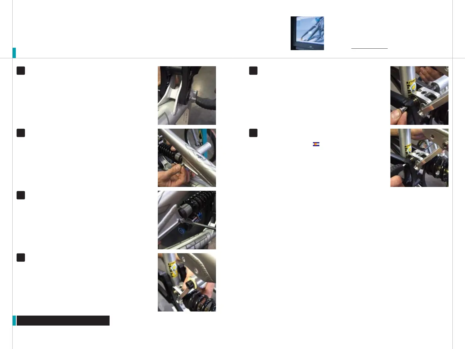
FRAME ASSEMBLY Thread a male Yeti bolt into the 22mm female bolt
and tighten down with the 5mm allen keys. The shoulder on the bolt
should not be visible. The bolt should fit flush against the frame
Torque spec: 125-150 inch pounds.
FRAME ASSEMBLY
Slide the machined sleeve into the IGUS bushing
on the top of the Dogbone. Then repeat step 3 (bolt insertion and
retention) fro this mounting location. At this time you can choose either
position the 6.5” travel or the 7.3” travel position.
FRAME ASSEMBLY Rotate the swing arm up towards the Ratelink
and line through holes on the swingarm with the steel pin on the
Ratelink. Then slide the 5/16 dickey or 8mm allen key through the mounting
position to hold the shock assembly in place.
13
FRAME ASSEMBLY Thread a male Yeti bolt into the 43 mm female
bolt and tighten down with the 5mm allen keys
Torque spec: 125-150 inch pounds.
14
FRAME ASSEMBLY Place the black washer over the main pivot pin
as shown and thread the male button head on. Cinch the button head
down with a 5mm allen key while holding the opposing side with the 6mm
allen key. Prep all bolt threads with blue loctite prior to assembly
Torque spec: 125-150 inch pounds.
FRAME ASSEMBLY
Place the shock assembly onto the bike in the
configuration shown to the right. Slide the 5/16 guide or 8mm allen
key through mounting position one to hold the shock assembly in place
11
12
9
10