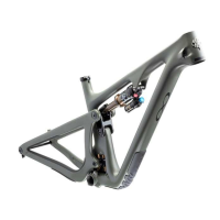
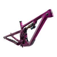
SB120 | OWNER’S MANUAL
10
16
Install Univesal Hanger (3.34) into frame.
Do not use grease. Note that hanger cap
bolt is reverse threaded.
Torque: 25 Nm
14
Install Housing Clamp Cap (3.8) onto the drive-
side main pivot axle with a M4 x 16L FHCS (3.23
Tighten until snug. Hardware can be torqued to
2-3 Nm after housing installation.
12
Install the shock into the frame by securing
front eyelet with a Guide Pin. Apply Loctite to
the threads and grease shaft of Small Collet
Axle (3.16). Install Shock Extender Screw (3.16)
through the lower extender tab, through the
Shock, and thread into the upper extender tab
(3.23). Use a socket bit extender to help gain
clearance between wrench and Link.
Torque: 12 Nm
Take precautions to prevent the shock striking/
contacting the downtube.
15
Install a Housing Clamp Cap (3.8) and Clamp
Base (3.6) onto the non-drive main pivot wedge
bolt with a M4 x 25L FHCS (3.24).
Tighten until snug. Hardware can be torqued to
2-3 Nm after housing installation.
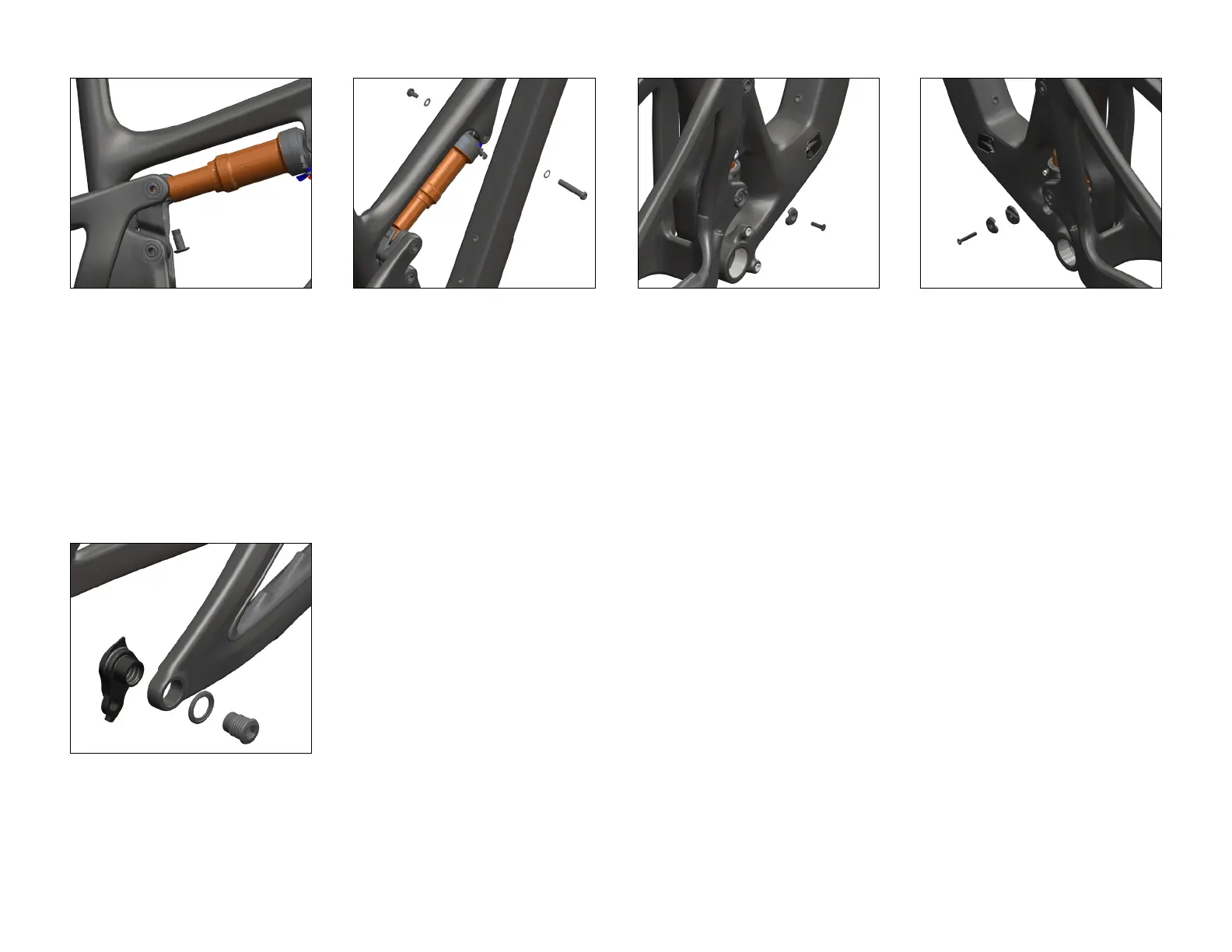
13
Install Female 8x45mm Bolt (3.18) with Washer
(3.21) through front Shock Eyelet and secure
with M6 Male Bolt (3.19) and Washer (3.20).
Apply Loctite to threads of M6 Male Bolt (3.19).
Torque: 10 Nm


 To Next Page