28. 29.
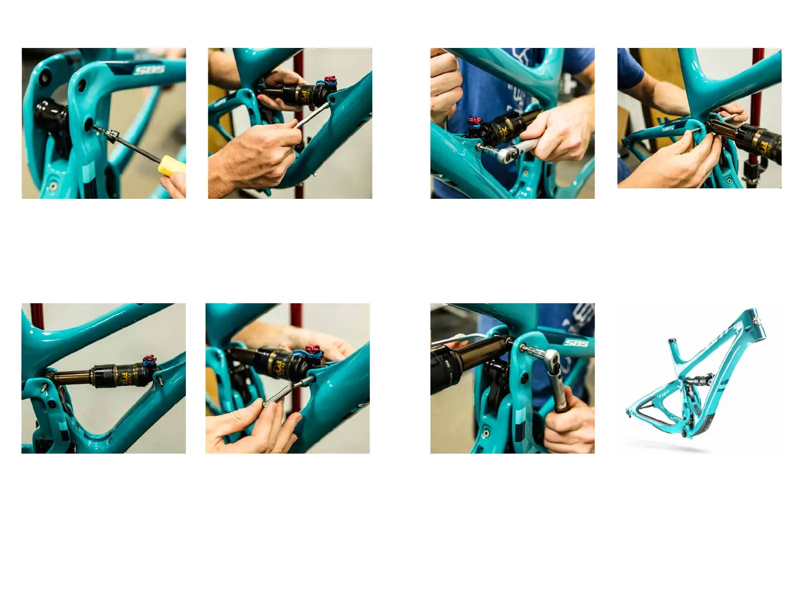
Slide the shock into place in the frame. Align the
front shock mount using a guide pin (200020118)
rst.
With the front mount guide pin in place, align rear
shock mount with a second guide pin. NOTE: If
a second guide pin is not available simply install
the front mount hardware (see steps 24 and 25)
and re use the guide pin in rear shock mount.
Place a 8.5mm x 12.5mm washer (300030069)
over the front shock mounting pin (300030153)
and slide the mounting pin over the blunt end of
the guide pin, pushing it through the frame.
22.
23.
24.
ASSEMBLY
21.
Grease the threads and collet wedge on the
upper link collet bolt (300040486) and thread it
into the upper link pivot collet axle with a 4mm
allen wrench. Firmly tighten by hand and nish
with a torque wrench.
*Torque to 8 Nm
ASSEMBLY
Place the 6.5mm x 12.5 washer (300030062) over
a Male Ti bolt (300030151). Apply Blue Loctite
to the threads. Using two 5mm allen wrenches
tighten the male bolt into the shock mounting pin.
Finish using a torque wrench.
*Torque to 7 Nm
25.
Thread a Male Ti bolt (300030151) into the rear
shock mounting pin (300030289) and thread all
the way in. Place a 8.5mm x 12.5mm washer
(300030069) over the shock mounting pin
assembly and slide it through the swing arm and
shock using the blunt end of the guide pin to
guide it through.
26.
FRAME ASSEMBLY IS COMPLETE.
Place the 6.5mm x 12.5 washer (300030062) over
a Male Ti bolt (300030151). Apply Blue Loctite
to the threads. Using two 5mm allen wrenches
tighten the male bolt into the shock mounting pin
assembly. Finish using a torque wrench.
*Torque to 7 Nm
27.