— 12 —
IM 2041-01
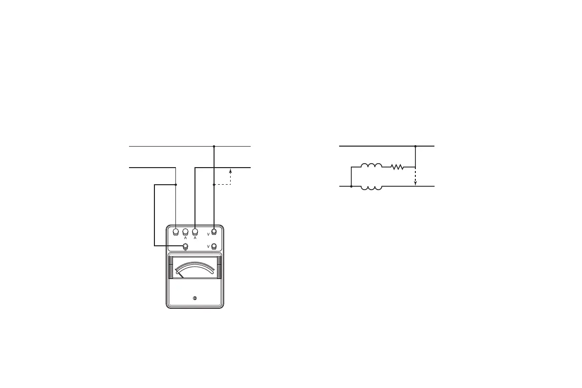
(2) 電流コイルが負荷側に結線された場合の補償
Fig. 3-3 のように電流コイルを電圧コイルより負荷側に結線した場合,
電圧結線の接続点 P を Q 点に変えると電力計の指示は電流コイルの
損失を示します。この値を始めの指示値から引けば真の負荷電力を
求めることができます。
2. Correction when the current coil is connected to the load side
If the current coil is connected to the load side through the voltage coil as
shown in Fig. 3-3 and the voltage connection is moved from P to Q, the
wattmeter will indicate the power loss of the current coil. Subtract this
value from the reading on the scale to obtain the true load power.
±
±
電源
負荷
Load
電源
Power Source
負荷
MC
FC
V
A
Q
Q
MC: 電圧コイル Voltage Coil
FC: 電流コイル Current Coil
±
±
 Loading...


