15
IM 12B06J03-02EN-P
Remarks:
1 No revision to this drawing without prior approval of FM.
2 Installation must be in accordance with the National Electrical Code (ANSI/NFPA 70),
ANSI/ISA-RP12.06.01, and relevant local codes.
3 The sensor shall be installed to a certified intrinsically safe Smart Adapter, model
SA11-P1 with the following maximum values: Uo= 6.6 V, Io = 100 mA, Po = 165 mW.
4 The installers shall take necessary measures to prevent the possibility of sparking
resulting from differing earth potentials between the sensors and interconnecting
equipment. The sensor itself does not provide 500 V rms isolation from earth, the
interconnecting equipment Model SA11-P1 Smart Adapter however provide this
required isolation.
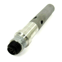
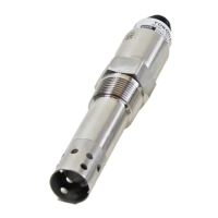
5 Sensor Model code:
Table 4:
VS Connector with ID-chip
Temperature sensor
+ Region:
T1 Pt1000, IS for ATEX/IECEx, FM-US,
FM-CAN
NPT PPS body/Tapered Thread/
Dome shaped
FSM PPS body/Tapered Thread/Flat Surface
FTD PVDF body/Tapered Thread
Dome shaped
Up to ten alphanumeric characters
(A to Z, 0 to 9 or hyphen)
6 WARNING-POTENTIONAL ELECTROSTATIC CHARGING HAZARD SEE
INSTRUCTIONS
pH sensors containing accessible plastic parts and/or external conductive parts, must
be installed and used in such a way, that dangers of ignition due to hazardous
electrostatic charges cannot occur, especially in the case that the process medium is
non-conductive.

 Loading...