21
IM 12B06J03-02EN-P
3. INSTALLATION OF FU20
For optimum measurement results, the
FU20 should be installed in a location that
offers an acceptable representation of the
process composition and DOES NOT
exceed the specifications of the sensor.
threaded connections on both ends of the
sensor to allow installation in a wide
variety of applications.
3.1 Typical installation
The FU20 sensor is designed for versatile
in-line, immersion or off-line installation.
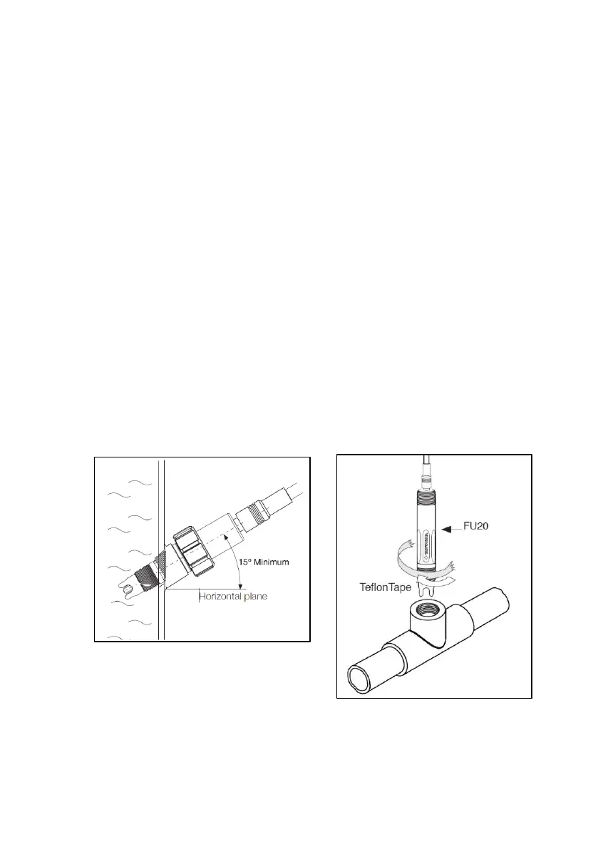
For best results the FU20 should be
mounted with the process flow coming
towards the sensor.
For the Fixed cable versions requires
installation of the sensor positioned at
least 15° above the horizontal plane to
eliminate air bubbles in the pH glass bulb
(see Figure 3).
The models type VP and VS can be
mounted in all angles with respect to the
horizontal plane including Upside Down.
Figure 3: Sensor installation
3.2 Preparing the sensor for use
Remove the sensor from its shipping box
and slide of the so-
tube filled with solution to prevent drying
out of the measuring elements during
shipment or storage. Although on the
Quality Inspection Certificate (QIC) all
factory calibration data is stored, it is
recommended to calibrate the sensor
before first use. A general calibration
procedure is described in Section 6 of this
Instruction Manual.
3.3 Mounting the sensor
The simplest mounting is to use one of
sensor. Apply Teflon tape to the
appropriate threaded end, then install the
sensor in the process Tighten the sensor
using a wrench on the sensor flats. (see
Figure 4).
Note: Do not overtighten the sensor
body. Max. torque applicable in paragraph
2.9
Figure 4: Simple mounting of sensor

 Loading...