11
IM 12D06D05-01E
3 INSTALLATIONANDWIRING
3-4. Wiring the contact signals
3-4-1. General precautions
The contact output signals consist of volt-
age-free relay contacts for switching electrical
appliances(SPDT).Theycanalsobeusedas
digital outputs to signal processing equipment
(suchasacontrollerorPLC).Itispossibleto
use multi-core cables for the contact in and
output signals and shielded multi-core cable for
the analog signals.
3-4-2. Contact outputs
TheEXAxt450unit’sfourcontacts(switches)
that can be wired and configured to suit user
requirements.ContactS4isprogrammedas
a fail-safe contact. Please refer to section 5-7,
Contact output setup for functionality descrip-
tion.
Alarm (limits monitoring)
Contactsconfiguredas“ALARM”canbeener-
gized when limits are crossed.
Fail
Contactsconfiguredas“FAIL”willbeenergized
whenafailsituationoccurs.Somefailsitua-
tions are automatically signaled by the internal
diagnostics (electronics) of the converter.
Otherscanbeconfiguredbytheuser(see
section5-11ErrorConfiguration).Bypressing
the“INFO”buttononthemainscreentheuser
is given an explanation as well as a remedy for
the current fail situation. Always connect the fail
contact to an alarm device such as a warning
light, alarm bell or displayed on an annunciator.
“ALARM” Contact “FAIL” Contact
PowerOff NC NC
PowerOn NC NC
Alarm NO NC
Fail NC NO
FailandAlarm NC* NO
HOLD NC NC
* Whenafailsituationoccurswhichisrelated
to the parameter associated with the contact
(Conductivity, Concentration or temperature)
the contact will go to NC. When the fail
situation is not related to the parameter
associated with the contact the contact will
remain in the state it is currently in.
3-4-3. Contact input
It is necessary to use screening/shielding on
the input signal cables. Terminal 63 is used to
connect the shielding.
3-5. Wiring the mA-output signals
3-5-1. General precautions
The analog output signals of the EXAxt
transmit low power standard industry signals to
peripherals like control systems or strip-chart
recorders(Figure3-6).
3-5-2. Analog output signals
The output signals consist of active current
signalsof4-20mA.Themaximumloadcanbe
600 ohms on each.
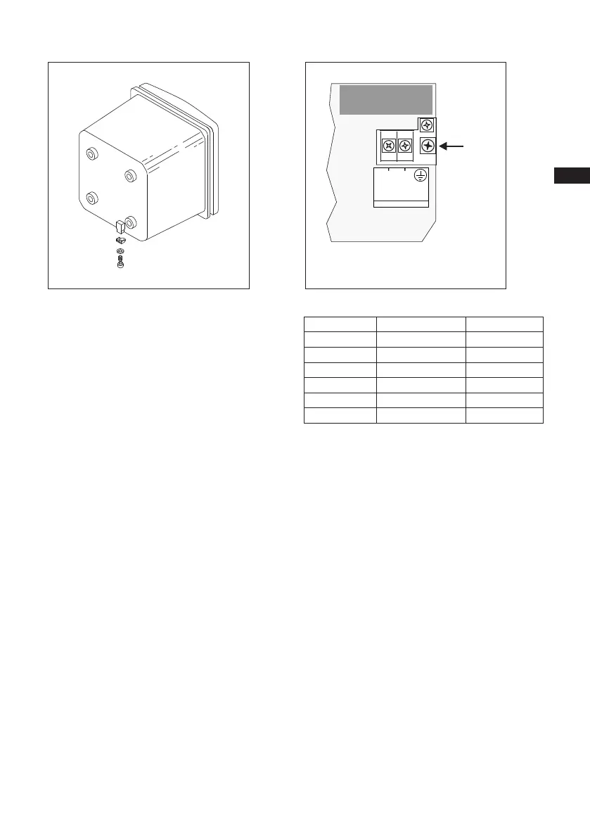
(M4screw)
Figure 3-8-a. External grounding Figure 3-8-b. Internal grounding
2
N
1
L
POWER
100-240 VAC/15 VA/ 50/60Hz
FUSE: 500 mA/250 VAC/T
AC
(M4screw)

 Loading...
