26
IM 12D06D05-01E
Expire time
Iftheoutputisover100%forlongerthanthe
expiretime,theoutputwillreturnto0%.
Damping time
The response to a step input change reaches
approximately 90 percent of its final value
within the damping time.
100%
0%
set
point
process
value
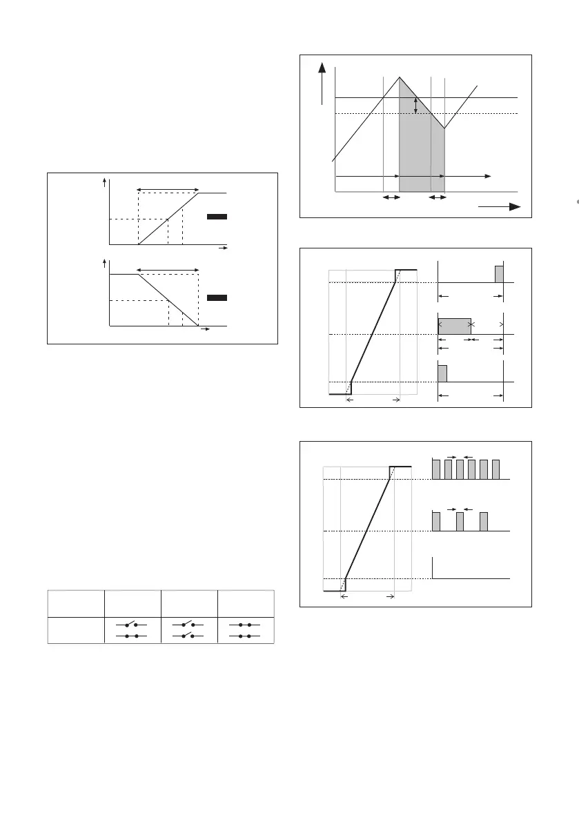
Direct
100%
0%
set
point
process
value
Reverse
range
range
manual
reset
manual
reset
Figure 5-2. Direct/Reverse action
5-7. Contact output setup
S1/S2/S3/S4
EachSwitch(contact)canhavethefollowing
functions.
1. Control : A selection of P- PI- or PID control
2.Alarm :LoworhighvalueLimitsmonitoring
3. Hold : A hold contact is energised when
theinstrumentisinHOLD
4.Fail :S4issetasfail-safecontact.
6.
Simulate
: To test the operation of the contact,
simulate can be used. The contact
can be switched on or off or a
percentage of duty cycle can be
entered (DC period time)
7.Off :Switchisnotused.
power on
power on
power down
normal opened
contact
activated
S1, S2, S3
S4
Above table shows contact output status between common to NO.
Configure hold
Hold is the procedure to set the outputs to
a known state when going into commission-
ing.DuringcommissioningHOLDisalways
enabled, out puts will have a fixed or last value.
DuringcalibrationthesameHOLDfunction
applies.Forcalibration,itisuptotheuserif
HOLDisenabledornot.
Lifetime contacts
Oneshouldnotethatthelifetimeofthecon-
tacts is limited (10
6
). When these contacts are
used for control (pulse frequency or duty cycle
with small interval times), the lifetime of these
contactshouldbeobserved.On/Offcontrolis
preferred over Pulse/duty cycle.
Setpoint
Hys.
SC
off on off
Delay time Delay time
t (sec)
100
50
0
t
on
t
off
50%
50%
% controller output
Range
Duty cycle
t
on
> 0.1 sec
Duty cycle
t
off
> 0.1 sec
Duty cycle
100
50
0
% controller output
Range
0.3 s
Maximum pulse frequency
50% pulse frequency
No pulses
0.3 s
Figure 5-3. Alarm contact (on/off control)
Figure 5-4. Duty cycle control
Figure 5-5. Pulse frequency control

 Loading...
