Quick Reference Instruction Manual
Installation
Sensor installation
18 / 54
IM01U10A00-00EN-R, 2nd edition, 2017-08-29
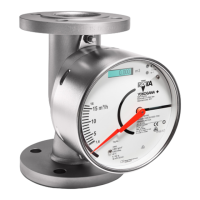
Fixing the flange
▶ Use screws and nuts suitable for the flanges.
▶ In case the nominal width of the piping deviates from the flow meter, use the appropri-
ate reductions.
▶ Inner gasket diameters should not fall below the inner diameters of the flange.
Fig.11: Fixing the flange
1 Pipe flange
2 Gasket
3 Sensor flange
4 Bolt
5 Nut
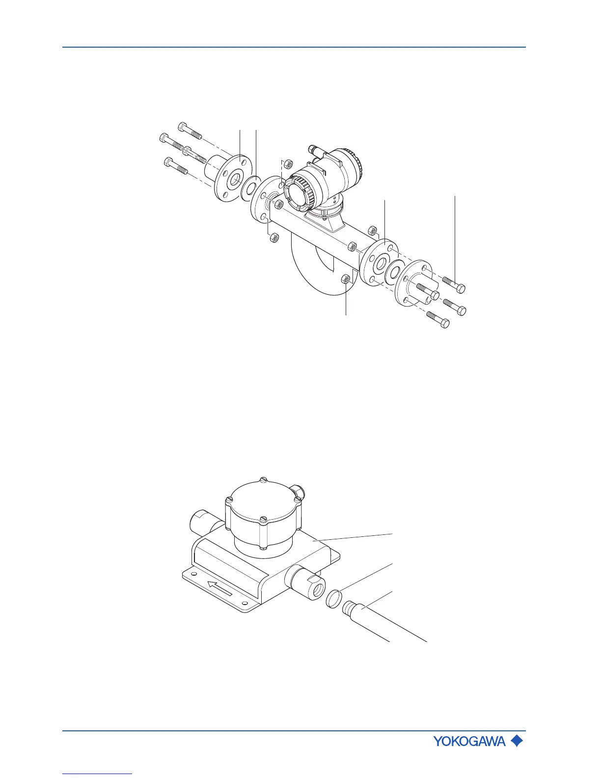
Internal thread
connection
For process connections with an internal thread, the connection must be installed in ac-
cordance with the following figure.
 Loading...