Do you have a question about the YOKOGAWA CW240 and is the answer not in the manual?
Important information and disclaimers regarding manual content and usage.
Details about identifying the main unit and its specifications.
Lists available model variants and their corresponding suffix codes.
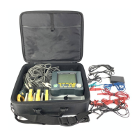
Illustrates how to pack the main unit and accessories into a carrying case.
Explains warning, caution, and safety symbols used in the manual and on the device.
Provides critical warnings for instrument usage, power sources, and handling.
Provides a general description of the CW240 clamp-on power meter and its capabilities.
Illustrates the interconnected components and peripherals of the CW240 system.
Identifies and describes the main components on the front panel and connector interfaces.
Details the function and purpose of each key on the instrument's control panel.
Illustrates the layout and structure of the device's display screens.
Explains how the instrument indicates overrange conditions or measurement errors.
General guidelines for safe handling, operation, and maintenance of the instrument.
Instructions on how to connect the instrument to power sources, including AC adapter and batteries.
Step-by-step guide for safely connecting voltage probes to the circuit and instrument.
Instructions for safely connecting clamp-on probes to the measurement circuit and instrument.
Procedure for powering on the CW240, including startup screens and self-check.
Tips and conditions for achieving higher precision during measurements.
Essential safety guidelines before making wiring connections to the measurement circuit.
Guidelines for installing the CW240 in suitable environmental conditions.
Procedure for configuring the wiring system settings on the GENERAL 1/2 screen.
Detailed steps and safety warnings for performing the actual wiring connections.
Procedure for verifying the correctness of wiring connections using the instrument's function.
Instructions on how to directly set the voltage measurement range using dedicated keys.
Procedure for directly setting the current measurement range using dedicated keys.
Describes the available ranges and display digit configurations for various measurements.
Overview of the initial setup required before making measurements, including data save and conditions.
Configuration options for general settings, including wiring, loads, and ranges.
Further general settings covering measurement methods, sampling, and display options.
Configuration options for saving measured data, including start/stop times and destinations.
Configuration of RS-232 communication parameters for PC or printer connection.
Setup for voltage quality measurements, including enabling, threshold, and hysteresis.
Configuration options for hardware-related features like language, beep, backlight, LCD contrast, and ID.
Overview of measurement capabilities, including integration and instantaneous measurements.
Description of the different screens available for displaying measurement results.
Procedure to measure electric energy by setting integration start and stop times.
Procedure to measure demand values and interval electric energy by setting integration parameters.
Function to magnify and view specific measured values in detail.
Procedure for analyzing and displaying harmonic measurements (1st to 50th order).
Procedure to display voltage and current waveforms (U&I, U, or I).
Procedure to measure and display voltage quality events like dips, swells, and interruptions.
Procedure to check configured settings before starting a measurement.
Overview of saving measured data and setting values to PC card or internal memory.
Explains manual and automatic saving methods for measured data.
Details the backup memory function for PC card data and its operation during integration.
Procedure for copying the current display screen, saving it as a bitmap file.
Overview of file management operations: name change, delete, format, copy, and setting files.
Procedure to change the name of a saved file.
Procedure to select and delete saved files from internal memory or PC card.
Procedure to format internal memory or PC card for file system use.
Comprehensive guide to managing setting files: loading, saving, deleting, and renaming.
Overview of connecting the CW240 to a PC or printer via RS-232 for data transfer and setup.
Instructions on connecting and using a personal computer with the CW240 for data transfer and setup.
Instructions on connecting and using a printer with the CW240 for outputting data and settings.
Details on PC card interface standards and confirmed compatible PC cards.
Instructions for correctly inserting and removing PC cards from the device.
Procedure for formatting a PC card before use, essential for file processing.
Instructions on saving measurement data and setting values to a PC card, including file processing.
Overview of controlling integration measurement externally and synchronizing multiple units.
Instructions on how to connect external control signals to the instrument's terminals.
Information on the CW240's analog output capabilities for converting measurements to DC voltage signals.
Details on the CW240's analog input function for measuring DC voltage signals.
Instructions and diagrams for connecting analog input/output signals to the instrument.
Describes the function that saves data and settings if power is interrupted during integration measurement.
Function to freeze the current display values on the screen.
Procedure to manually turn the LCD backlight on or off, and details on the auto-off function.
Function to lock the keys to prevent accidental operation during measurements.
Procedure to reset the instrument's settings to factory defaults.
Guide to troubleshooting common issues and checking potential causes of malfunction.
Lists error messages and the corresponding actions or solutions.
Detailed technical specifications for the CW240 power meter.
Technical specifications for the various clamp-on probes compatible with the CW240.
Provides a visual representation of the CW240's internal hardware components and their connections.
Describes the format of setting files saved by the CW240.
Details the format of measurement data files saved manually, including header and data sections.
Describes the format for standard interval time measurement data files.
Format details for normal measurement data across various wiring configurations.
Format details for harmonic measurement data across various wiring configurations.
Format details for harmonic measurement data specific to 3P3W+1P3W wiring.
Format details for normal measurement data specific to 3P3W+1P3W wiring.
Format details for harmonic measurement data specific to 3P3W+1P3W wiring.
Format details for voltage fluctuation measurement data.
Describes the format of data printed to an external printer.
Explains how polarity is expressed for active power, reactive power, power factor, and phase angle.
Details polarity determination for voltage phase angle, current phase angle, and harmonic power.
Explains the two methods for calculating reactive power and their implications.
Describes the sampling methods: PLL synchronization and fixed clock, and PLL unlock conditions.
Provides definitions for symbols, units, items, and content used in the manual.
| Brand | YOKOGAWA |
|---|---|
| Model | CW240 |
| Category | Measuring Instruments |
| Language | English |