4-24
IM CW240E
4.7 Checking Wiring
WARNING
Checking wiring is important for ensuring safe and accurate measurements.
Refer to Chapters 3 and 4 to carry out the necessary precautions for safe
measurement and ensure that the connections have been made correctly.
Check that the connections of the voltage probes and the connector H/L
orientation and measurement positions of the clamp-on probe are
correct.
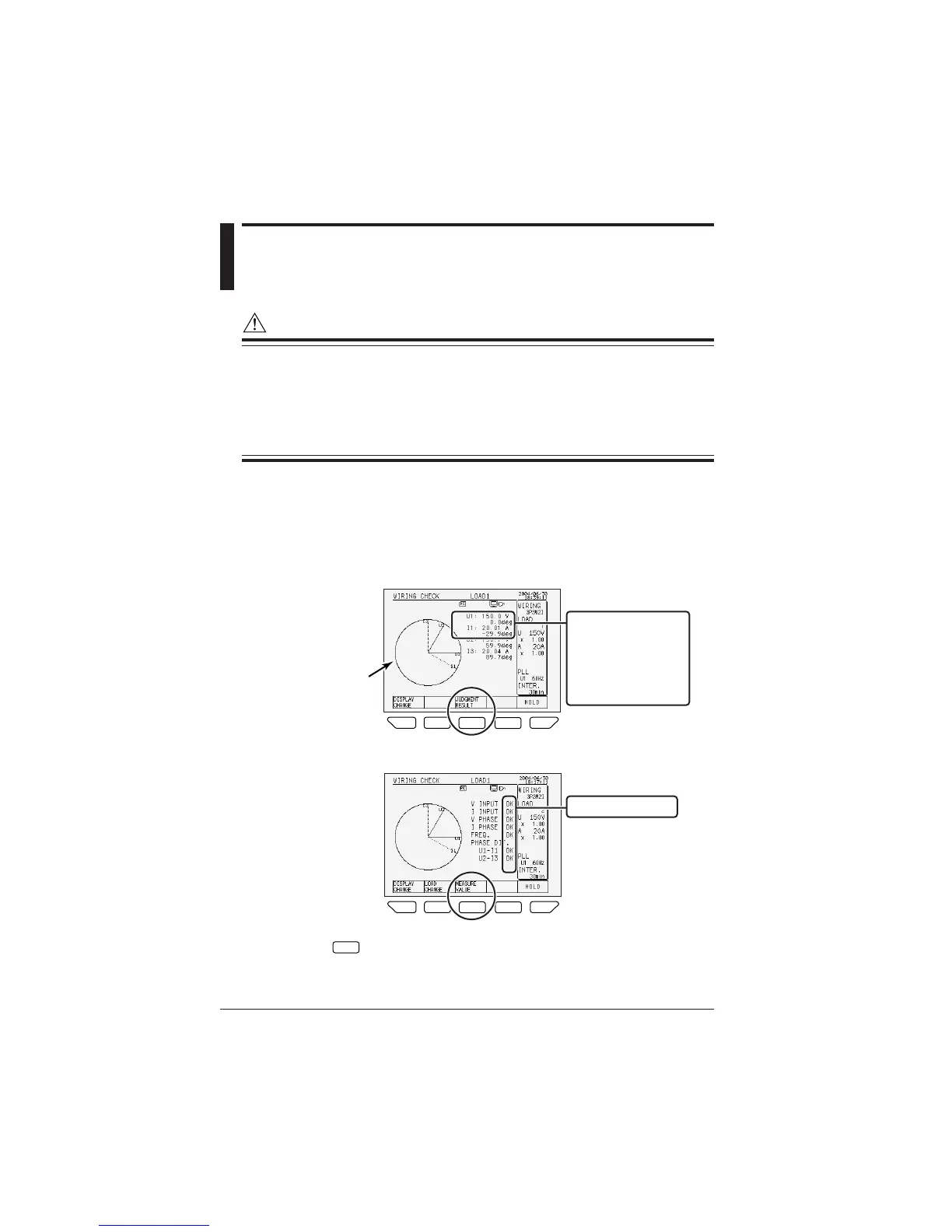
• Press the F1 key (DISPLAY CHANGE) on the MEASURE screen to select the
WIRING CHECK screen.
• The following item is indicated on WIRING CHECK screen.
Rms value of voltage input and Current input, and phase angle and vector
diagram related to U1.
<Measured value display>
F
1
F
1
F
2
F
3
F
4
F
5
Voltage(rms):U1
Phase angle
(relative to U1)
Current(rms):I1
Phase angle
(relative to U1)
vector diagram
displayed
<Judgment result display>
F1F1
F2
F3 F 4
F5
Judgment result
Use the
F3
key to switch between the measured value and judgment
result displays.
To change the wiring to 3P3W+1P3W (Scott connection), press the F4 key to
display the connection destination of a single-phase load.

 Loading...