4-25
IM CW240E
Wiring
4
NOTE
• As the CW240 performs a wiring check based on the conditions shown below
to judge if the wiring is accepted (OK) or rejected (NG), there may be cases
where the result of the check may show what is actually correct wiring as NG
and vice versa.
For this reason, also check for an error in the vector diagram or measured
values.
• The rms values, phase angles, and vector diagram displayed are based on the
fundamental components of voltage and current inputs.
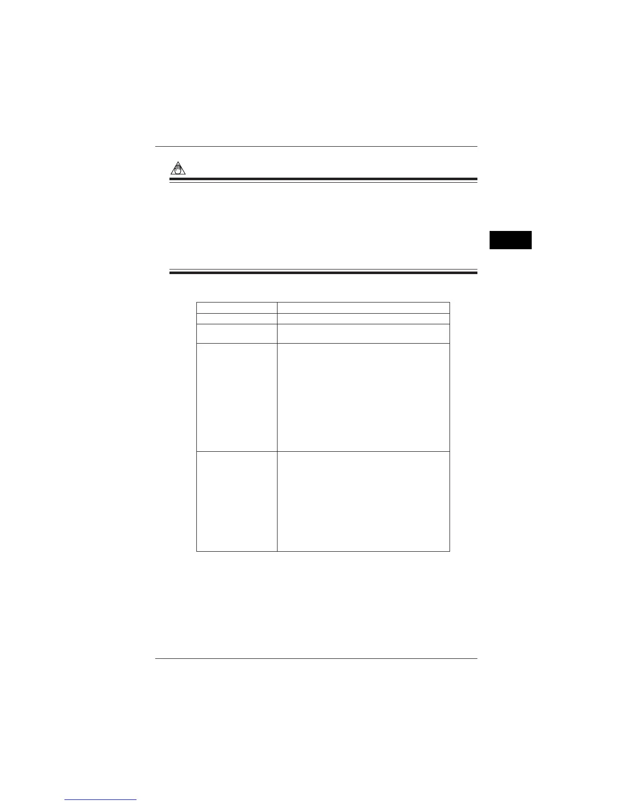
● Wiring Check Items and Error Conditions - 1
10% or less of the rated range
Error Conditions
1% or less of the rated range For 1P3W3I or 3P4W4I,
I4 is not judged.
• The result of voltage input judgment is NG.
• For any system other than 3P3W2I or 3P3W3I:
Each current does not fall within a range of ±60° based
on each phase voltage
• For 3P3W2I:
I1 does not fall within a range of +90° to -30° relative to U1
I3 dose not fall within a range of +90° to -30° relative to U2
• For 3P3W3I:
Each current does not fall within a range of +90° to -30°
based on each phase voltage
• For Scott connections:
A combination of single-phase 3-wire and three-phase
3-wire 2-current
• The result of voltage input judgment is NG.
• For 1P3W or 1P3W3I:
U2 does not fall within a range of 180° ±20% with
respect to U1.
• For 3P3W2I:
U2 leads U1 and does not fall within a range of 60°
(leading)
± approx. 20° relative to U1.
• For 3P3W3I, 3P4W, or 3P4W4I:
U2 lags behind U1 and does not fall within a range of
120°(lagging) ± approx. 20° relative to U1, or U3 leads
U1 and does not fall within a range of 120°(leading)
± approx. 20° relative to U1.
Item
Voltage input
Current inpu
Phase difference
(voltage - current)
Voltage phase
4.7 Checking Wiring

 Loading...