12-3
IM CW240E
Using External Control Input/Output
12
12.2 Connecting External Control
Terminals
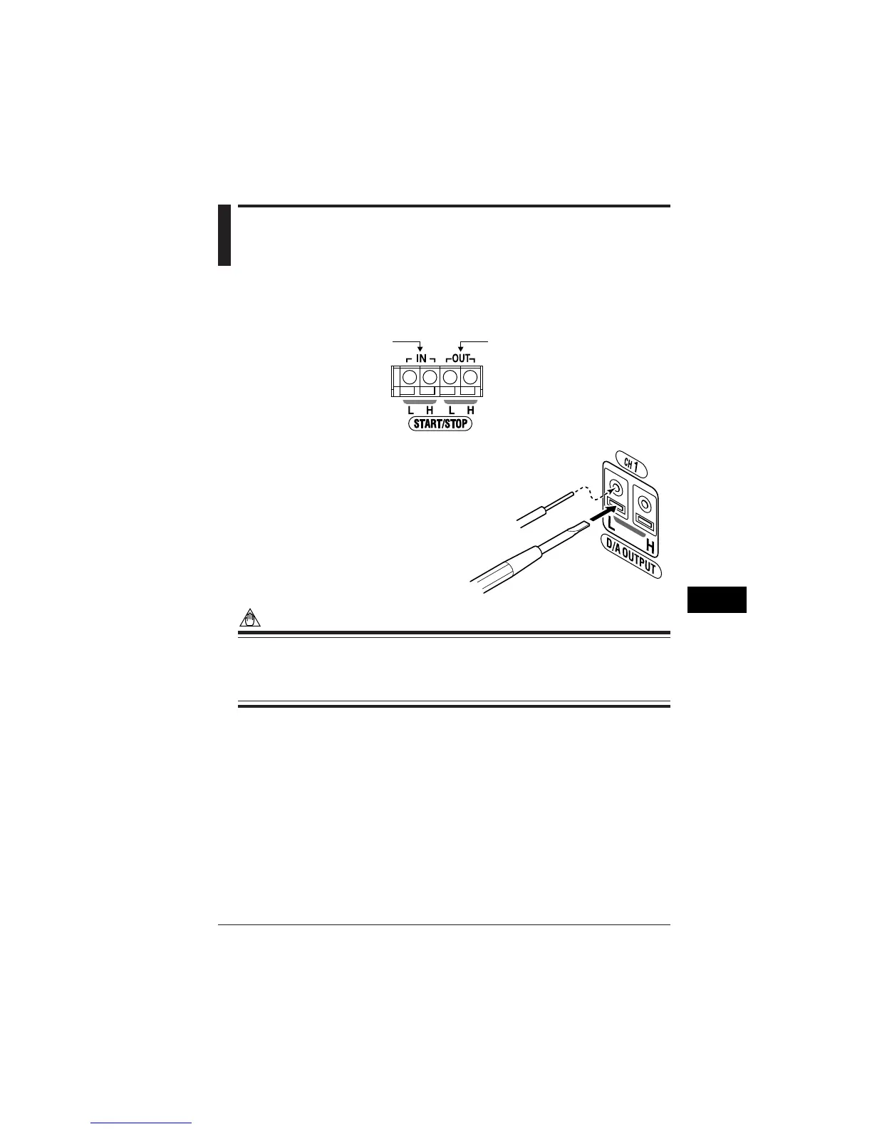
● Terminal Diagram
Output terminalsInput terminals
● Connection Method
<1>
Insert the signal line while pressing the
rectangular portion at the bottom of the
terminal with a flathead screwdriver, etc.
<2>
The signal line is secured when the
screwdriver is removed.
NOTE
• The input circuit may be damaged if voltage exceeding the allowable input
voltage range (---S0.5 to 5.5V) of the signal input terminal is input.
• Be careful not to mistake the input terminal and the output terminal when mak-
ing connections.
● Usable Signal Lines
Suitable wiring : Solid wire φ1.0 (AWG18); Stranded wire 0.75 mm
2
Usable wiring : Solid wire φ0.4 to 1.0 (AWG26 18)
Stranded wire 0.3 to 0.75 mm
2
(AWG22 20)
Strand diameter φ0.18 or higher
Standard stripped wire length 10 mm
Signal line
Flathead screwdriver, etc.

 Loading...