7-6
IM CW240E
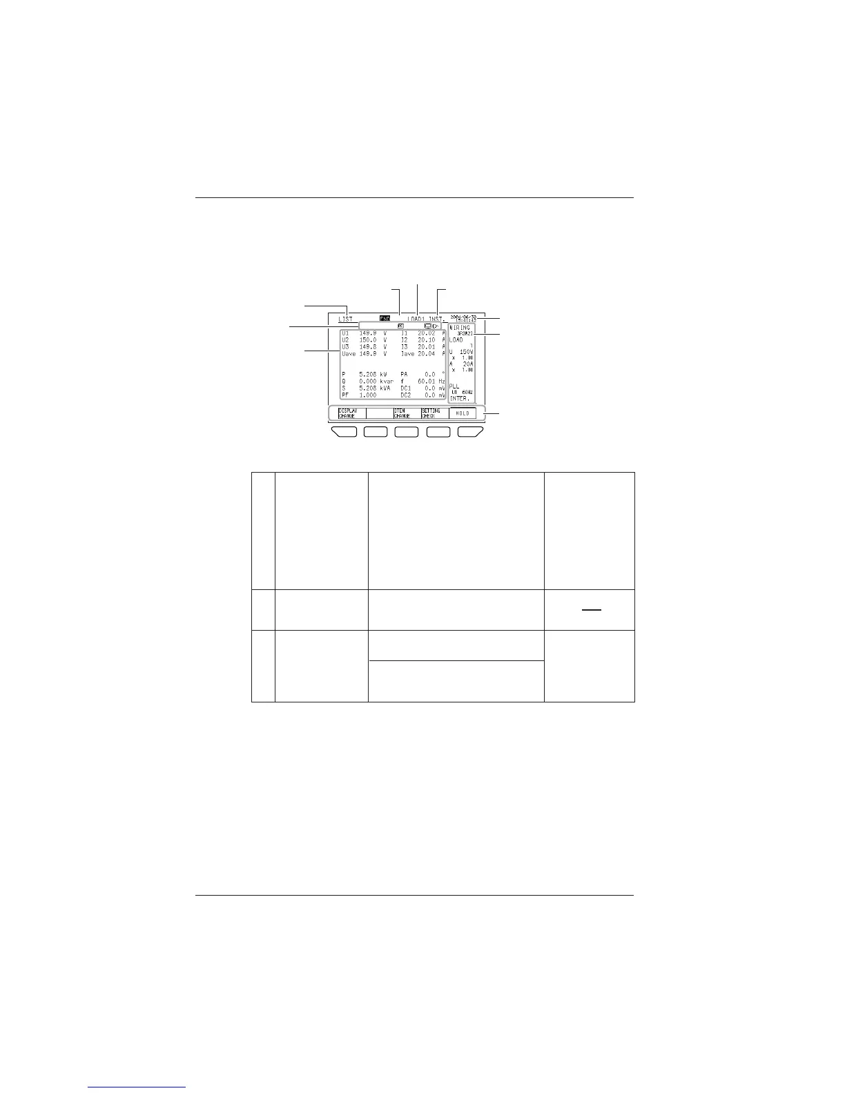
7.2.2 Description of Display
● Description of Display
F
1
F
1
F
2
F
3
F
4
F
5
6. Mark
7. Measured
values
5.
Date and time
3. Number of loads
4. Items
8.
Common setting items
9.
Function key labels
1.Selectable
screens
2. Integration measurement state
● Display Information
Selectable screens
F1 (DISPLAY CHANGE)
LIST
POWER
INTEGRATE
DEMAND
ZOOM
HARMONIC (LIST, GRAPH, VECTOR)
WAVEFORM (U&I, U, I)
VOLT. QUALITY
WIRING DIAG.
WIRING CHECK
1
Integration
measurement state
STANDBY
INTEG.
END
2
Number of loads
F2 (LOAD CHANGE)
LOAD (no switching is made in the case
of a single load)
If wiring is a Scott connection, switching
is made between the 3-phase side (3P3W)
and single-phase side (1P3W).
3
7.2 Measure Screens

 Loading...