7-7
IM CW240E
Measurements
7
*1 If a Scott connection (3P3W + 1P3W) is selected for wiring
*2 If the fixed clock is selected for the sampling method
Date and time This field shows the current date and time.
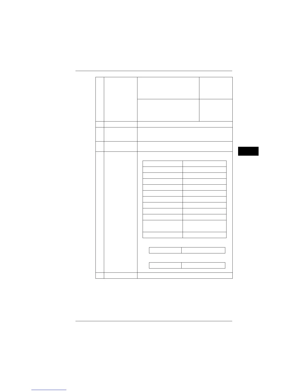
Display Example
R-S 1P connection
50Hz Fixed clock frequency
3P3W2I Wiring
1 Number of loads *1
U 150V Voltage range
⫻ 001.00 VT ratio
A 50A Current range
⫻ 001.00 CT ratio
I4 500mA I4 current range
⫻ 001.00 I4 CT ratio
PLL Sampling method *2
U1 50Hz
Frequency source
(Fixed clock) frequency
Interval 30 min Interval time
Description
5
Mark
This field shows a mark.
For more information on marks, see Section 2.6, Description of
Mark Indication.
6
Measured values
This area displays measured values, a graph, a vector diagram,
or waveform.
7
Common setting items
Setting Items
8
Function keys
This area displays items corresponding to the function keys (F1 to F5).
9
Items
F2 (ITEM CHANGE)
F3 (ITEM CHANGE)
For the List and Power screens
INST.
AVE
MAX.
MIN.
4
For the Volt. Quality screen
ALL
SWELL
DIP
INTER.
7.2 Measure Screens

 Loading...