12-2
IM CW240E
12.1 External Control Input/Output
The start and end of integration measurement can be controlled externally.
Also, the start and end of integration measurement can be synchronized when
using multiple units of this device.
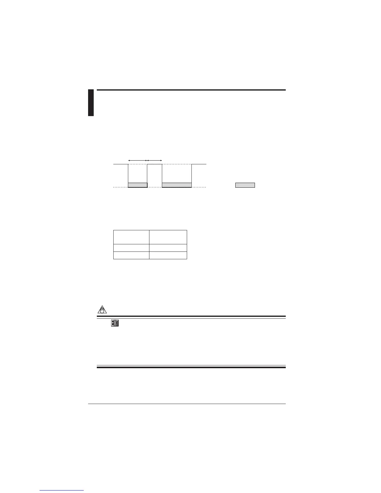
● Input/Output Signal Example
SEC.
StartStart Stop
5V
(Open)
0V
(Short)
Integrating
Stop
MIN.
<Input>
The control input signal is 0 V/5 V (Low/High), or terminal Short/Open.
Integration measurement is performed when the external control input is Low or
Short, and is stopped when the input is High or Open.
Input Level
Allowable Voltage
–
0.5 to 5.5 V
Minimum Time
Seconds
Low: 0.0 to 0.8 V
High: 2.0 to 5.0 V
<Output>
The control output signal is 0V/5V (Low/High).
It is Low when integration measurement is being performed, and High when not
being performed.
NOTE
• The mark is displayed when integration is being performed through the
external control signal.
• Start/end of integration through the external control signal takes priority over
manual or time-and-date settings.
• The external control signal is valid even during integration standby or when
the setup screen is displayed. However, it is invalid while integration mea-
surement is being performed.
Chapter 12 Using External Control Input/Output

 Loading...