Do you have a question about the YOKOGAWA AQ6370D and is the answer not in the manual?
Explains safety markings used in the manual for user safety and instrument protection.
Describes notations used to distinguish procedures from their explanations in operating chapters.
Explains panel keys and soft keys, and units like k and K.
Details on installing the instrument, turning it on/off, and wavelength calibration.
Covers auto sweep, other settings, measurement start, and external trigger.
Explains how to display and adjust waveforms, including markers and searching.
Covers waveform analysis and Go/No-Go judgment procedures.
Details on using storage media and saving data.
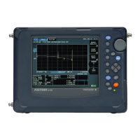
Describes the components and functions of the instrument's front panel.
Details the various connectors and ports on the rear panel of the instrument.
Explains the functions of the various keys and knobs on the instrument's panel.
Describes the layout and function of the instrument's LCD screen elements.
Illustrates the instrument's system structure and external connections.
Details various measurement functions like alignment, calibration, auto measurement, and sweeps.
Explains how to zoom, overview, and manage waveform traces and their modes.
Covers various analysis types like spectrum width, notch width, device analysis, and WDM analysis.
Describes other functions like USB mouse, soft key registration, data initialization, help, and locking keys.
Provides instructions on installation conditions, handling precautions, and environmental requirements.
Details the procedure for attaching and removing optical connector adapters.
Explains how to connect USB mice, keyboards, and storage devices.
Covers power connection precautions, turning the instrument on/off, and shutdown procedures.
Details the procedure for connecting the DUT (Device Under Test) via optical fibers.
Explains how to perform alignment adjustment using built-in or external light sources.
Details the procedure for wavelength calibration using internal or external light sources.
Explains how to calibrate the instrument's resolution bandwidth.
Covers important considerations during measurement, like fiber types and NA.
Explains the forms and behavior of soft keys used in the instrument's menus.
Details how to use a connected mouse and external keyboard for instrument operation.
Explains how to enter numerical values and character strings using the DATA ENTRY section.
Covers setting the number of digits, transparent display, and changing display colors.
Explains how to display, enter, and change the date and time settings.
Describes how to automatically set optimal measuring conditions and perform measurement.
Details how to set horizontal axis units and measure wavelength to air or vacuum.
Explains how to display and set sub scales for differential or normalized waveforms.
Covers setting the reference level using soft keys or one-action keys.
Explains how to set the center wavelength or center frequency using soft keys or one-action keys.
Details methods for setting sweep width using SPAN, START/STOP keys, or one-action keys.
Explains how to set and correct wavelength or frequency resolution.
Covers setting the number of samples or sampling interval directly or automatically.
Explains how to set measurement sensitivity and CHOP mode settings.
Details how to adjust the sweep speed for faster measurements.
Explains how to set averaging times to improve S/N ratio.
Covers selecting traces, setting write/fix modes, and displaying traces.
Details how to start and stop sweeps, including segment measurement.
Explains how to specify a sweep range between line markers.
Covers methods for measuring pulse light, including peak hold and gate sampling.
Explains how to perform measurements synchronized with an external trigger signal.
Describes how to output trigger signals from the instrument.
Explains how to use the smoothing function to reduce noise in waveforms.
Details how to connect the instrument to an oscilloscope for analog voltage output.
Explains methods for zooming in/out on waveforms by specifying ranges or using the mouse.
Covers updating waveform data (write mode) and fixing it (fix mode).
Explains how to hold the maximum or minimum waveform values detected during sweeps.
Details how to set averaging times for improving S/N ratio.
Explains how to perform trace-to-trace calculations and display results.
Describes the normalized display function for comparing waveforms.
Explains how to perform curve fitting and peak curve fitting on trace waveforms.
Details how to compute and display power density in a specified bandwidth.
Covers displaying and manipulating moving, fixed, line, and advanced markers.
Explains how to split the screen for displaying multiple traces or ranges.
Details how to apply a noise mask to waveform parts or set display lower limit values.
Explains procedures for copying and clearing trace data.
Covers single peak/bottom searches and finding next/previous points.
Explains how to perform multi-peak/bottom searches and set detection thresholds.
Describes how to measure spectrum width using various algorithms and parameters.
Explains how to measure notch width (pass band/notch width) of filters.
Details how to measure the Side Mode Suppression Ratio (SMSR) for DFB-LDs.
Explains how to measure optical power by integrating waveform level values.
Covers analysis of parameters for different light sources like DFB-LD, FP-LD, and LED.
Explains how to measure Polarization Mode Dispersion (PMD) of optical fibers.
Details how to analyze WDM transmission signals, measuring channel wavelength, level, and SNR.
Explains how to measure optical amplifier gain and noise figure (NF).
Covers measuring optical filter characteristics, including peak and bottom analysis.
Explains how to create and edit standard and custom grid tables for analysis.
Describes measuring level fluctuations over time at a specific wavelength.
Explains how to create and use template data for Go/No-Go judgments.
Details how to specify analysis ranges between line markers or within zoom areas.
Covers setting wavelength and level shift amounts for correcting displayed values.
Explains how to log WDM, PEAK, DFB-LD analysis data, and save it to files.
Details supported USB storage media and procedures for safe removal.
Covers saving waveforms to internal memory and redisplaying saved data.
Explains how to save displayed waveforms to USB or internal memory and load them.
Details how to save all measured trace data to USB storage media.
Explains how to save and load instrument settings and soft key statuses.
Covers saving analysis results, including time and waveform data, in ASCII or binary format.
Explains how to save and load programs created with the program function.
Details how to save the instrument's screen as an image file (BMP or TIFF).
Covers saving and loading template files in CSV format for Go/No-Go judgment.
Explains how to save and load logging data and corresponding trace waveforms.
Describes how to create directories, copy files, change names, and sort files.
Explains how to register frequently used soft keys for easier access.
Details the procedures for restoring all settings to factory defaults.
Describes how to access help information for menus and soft keys.
Covers registering and loading preset character strings for menu inputs.
Explains how to lock and unlock instrument keys to prevent unauthorized operation.
Covers settings like UNCAL display, buzzer, language, auto offset, and network settings.
Details how to display system information, including firmware version and hardware details.
Explains how to update the instrument's firmware via USB or network.
Provides guidelines for performing mechanical inspections of the instrument's exterior and parts.
Describes checking the proper operation of each switch after turning the power ON.
Details how to check and calibrate the instrument's wavelength accuracy.
Explains how to check and verify the instrument's level accuracy using a light source.
Advises contacting the dealer for fuse replacement due to internal damage risk.
Covers cleaning the instrument's exterior and optical output section.
Provides guidelines for proper storage conditions to maintain instrument integrity.
Lists recommended replacement parts and their replacement periods.
Lists warning messages and their causes for troubleshooting instrument issues.
Lists detailed technical specifications for the instrument's performance and features.
Provides the physical dimensions and weight of the instrument.
Lists analytical functions that utilize GRID tables for analysis.
Describes the standard GRID table with predefined wavelength/frequency ranges.
Explains how users can edit and create custom GRID tables for analysis.
Details the THRESH method for calculating spectrum widths and center wavelengths.
Explains the ENVELOPE method for obtaining spectrum widths.
Details the RMS method for obtaining spectrum width and center wavelength.
Explains the PEAK RMS method for obtaining spectrum width and center wavelength.
Details the algorithms for NOTCH width measurement based on bottom or peak.
Describes the SMSR analysis function for DFB-LD light sources.
Explains the analysis algorithm for SMSR mode 1.
Explains the analysis algorithm for SMSR mode 2.
Explains the analysis algorithm for SMSR mode 3.
Explains the analysis algorithm for SMSR mode 4.
Details the POWER analysis function for calculating total power.
Explains the PMD analysis function for measuring Polarization Mode Dispersion.
Covers parameters analyzed for DFB-LD light sources.
Details parameters analyzed for FP-LD light sources.
Covers parameters analyzed for LED light sources.
Lists items analyzed in WDM waveforms, such as wavelength, level, and SNR.
Details parameters related to channel detection and SNR analysis for WDM.
Explains parameters like THRESH LEVEL, MODE DIFF, and DISPLAY MASK for WDM channel detection.
Details parameters for SNR analysis, including NOISE ALGO, NOISE AREA, and FITTING ALGO.
Explains display types like ABSOLUTE, RELATIVE, DRIFT(MEAS), and DRIFT(GRID).
Covers SIGNAL POWER and INTEGRAL RANGE settings for WDM analysis.
Describes the WDM analysis algorithm, including channel detection and noise level calculation.
Explains automatic setting functions for noise area and mask area.
Lists items analyzed for optical amplifiers, including gain and noise figure.
Details parameters related to channel detection for optical amplifier analysis.
Explains parameters for ASE level measurement, including OFFSET, ASE ALGO, and FITTING ALGO.
Details the FILTER PEAK analysis function for optical filters.
Lists items analyzed for optical filters, such as peak level, width, and crosstalk.
Details parameters for PEAK LEVEL, CENTER WL, SPECTRUM WIDTH, RIPPLE WIDTH, and CROSS TALK.
Describes algorithms for analysis like NOMINAL WAVELENGTH, XdB_STOP-BAND, XdB_PASS-BAND, RIPPLE, and CROSS TALK.
Details the FILTER BOTTOM analysis function for optical filters.
Shows the soft key tree for SWEEP related functions.
Shows the soft key tree for CENTER related functions.
Shows the soft key tree for SPAN related functions.
Shows the soft key tree for LEVEL related functions.
Displays the soft key tree for SETUP functions, covering various settings.
Shows the soft key tree for ZOOM functions.
Displays the soft key tree for DISPLAY functions.
Shows the soft key tree for TRACE management options.
Shows additional TRACE management options.
Displays the soft key tree for MARKER functions.
Shows the soft key tree for PEAK SEARCH functions.
Displays the soft key tree for ANALYSIS functions.
Shows the soft key tree for MEMORY operations.
Displays the soft key tree for FILE operations.
Shows the soft key tree for SETTING data management.
Displays the soft key tree for DATA management.
Shows the soft key tree for PROGRAM management.
Displays the soft key tree for GRAPHIC (screen image) saving.
Shows the soft key tree for TEMPLATE management.
Displays the soft key tree for LOGGING data management.
Shows the soft key tree for SYSTEM configuration options.
Displays additional SYSTEM configuration options.
Shows further SYSTEM configuration options.
Outlines restrictions on the use of the SOFTWARE for hazardous environments.
Explains security updates for Microsoft DRM and their impact on Secure Content.
Describes the use of NetMeeting, Remote Assistance, and Remote Desktop technologies.
Details Microsoft's policy on collecting and using technical information.
Explains the use of Internet gaming or update features and data authorization.
Covers software components enabling Internet-based services and automatic updates.
Mentions the ability to link to third-party sites and their non-endorsement.
Explains provision of Supplemental Components and terms of use.
Specifies limitations on processor usage and client connections for the SOFTWARE.
| Wavelength Range | 600 to 1700 nm |
|---|---|
| Wavelength Resolution | 0.02 nm |
| Level Accuracy | ±0.5 dB |
| Polarization Dependency | ±0.05 dB |
| Sensitivity | -90 dBm |
| Sweep Time | 0.2 sec (100 nm span) |
| Display | LCD |
| Interface | USB, GPIB |
| Wavelength Accuracy | ±0.02 nm |
| Dynamic Range | 78 dB (peak) |