Do you have a question about the YOKOGAWA ZR22G and is the answer not in the manual?
Describes immediate hazards and necessary precautions to avoid injury or death.
Highlights critical steps to prevent instrument damage or system failure.
Verifies instrument specifications against the order and checks for missing accessories.
Discusses factory-set parameters and necessary adjustments for operation.
Outlines user responsibilities for safe operation and product integrity.
Explains product usage terms and liability limitations.
Identifies the authorized representative in the European Economic Area.
Highlights the importance of the product's identification tag.
States the product is designed for users with specialized knowledge.
Explains battery disposal procedures according to EU directives.
Details system configurations based on operating conditions and safety requirements.
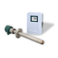
Lists major equipment and accessories for different system configurations.
Provides instructions for installing the general-purpose detector.
Details the installation process for the high-temperature detector.
Explains how to install the ZR802G converter unit.
Covers the installation of the ZA8F flow setting unit.
Describes the installation of the ZR40H automatic calibration unit.
Details the installation for the case assembly for calibration gas cylinders.
Outlines the procedure for performing an insulation resistance test.
Provides general wiring precautions and procedures.
Details specific wiring connections for the converter and detector.
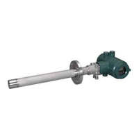
Describes the components of the ZR22G detector.
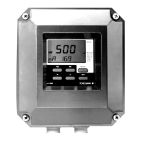
Outlines the components of the ZR802G converter.
Explains how to use the touch panel interface and its icons.
Describes the components of these auxiliary units.
Details the step-by-step process for starting up the analyzer from initial power-on.
Emphasizes verifying all connections before startup for correct operation.
Guides on setting up valves for proper gas flow and calibration.
Explains how to supply power and what to expect during the warm-up phase.
Describes how to confirm or change the converter's operating model (Oxygen/Humidity).
Guides on confirming or changing the detector type for proper measurement.
Explains setting for wet or dry gas measurements for Oxygen Analyzer.
Details how to set the analog output signal ranges (4-20mA).
Covers customizing the display items shown on the Home screen.
Describes setting the analog output range (4-20mA) for oxygen and humidity.
Explains how to hold analog output during specific operational states like warm-up or calibration.
Details setting upper and lower limits for the analog output signal.
Covers configuring various alarm types, limits, and output actions for abnormal conditions.
Describes how to configure contact outputs for alarms and other operational events.
Explains how to configure input contacts for external signals that trigger specific functions.
Covers miscellaneous settings including date/time, fuel parameters, and password protection.
Provides background on calibration principles for oxygen and humidity measurement.
Details the steps for performing manual, semi-automatic, and automatic calibrations.
Outlines the different calibration modes available and how to execute them.
Explains how to access and interpret detailed sensor data like correction ratios and cell robustness.
Describes the information available in the converter detail screens, including analog output and log data.
Covers viewing measurement trends and simple cell resistance trends.
Details display settings such as auto-return time, NE107 mode, and tag name entry.
Explains the blow back function for cleaning the probe, including mode and timing settings.
Details procedures for cleaning filters, tubes, and replacing sensor assemblies and heater units.
Covers inspection and maintenance for the converter, including fuse replacement and LCD adjustment.
Describes the process for replacing the flowmeter in the calibration unit.
Explains how to interpret fault codes and their corresponding remedies.
Details various alarms, their reasons, and troubleshooting steps.
Provides guidance on addressing abnormal readings not necessarily caused by equipment failure.
| Type | Zirconia Oxygen Analyzer |
|---|---|
| Response time | Less than 3 seconds (T90) |
| Power supply | 100-240 V AC, 50/60 Hz |
| Measurement object | Oxygen concentration in flue gas |
| Measurement Principle | Zirconia sensor |
| Output signal | 4-20 mA DC |
| Operating temperature | -20 to +60°C |
| Ambient Temperature | -20 to +50°C |
| Process Temperature | 0 to 700°C |
| Measurement Range | 0.1 ppm to 100% O2 |
