<8. Detailed Data Setting>
8-6
IM 11M12G01-02EN 1sh Edition : Mar. 25, 2021-00
(4) During Blow back (see Section “10.5 Blow Back”)
During semi-automatic blow back:
by using the touchpanel or entering a blow back start instruction by using a contact input, until the
blow back time and Hold time (output stabilization) elapse.
During automatic blow back:
blow back time and Hold time (output stabilization) elapse.
(5)
During Simple Cell Resistance Measurement (see Section “10.6 Simple cell resistance measurement”)
During semi-automatic simple cell resistance measurement
This starts when you press “Start” of the simple cell resistance measurement on the touch panel.
The measurement period lasts until the simple cell resistance measurement time and HOLD time
(output stabilization) elapse.
During automatic simple cell resistance measurement
This starts when you reach the simple cell resistance measurement start time. The period lasts
until the simple cell resistance measurement time and HOLD time (output stabilization) elapse.
(6) Fault
“Fault “ means that Fault (Power Supply supply to sensor heater is stopped) is occurring. For
more information on Fault or errors, See Chapter
“12. Troubleshooting”.
8.2.2 Preference Order of Output Hold Value
The output hold value takes the following preference order:
Fault is occurring.
Under calibration/ during blow back.
/Simple cell resistance measuring
Under maintenance
During warm-up
Preference order
High
For example, if the output current is set to 4 mA during maintenance, and no output-hold output for during
calibration is preset, the output is held at 4 mA during the maintenance display. However, the output hold is
released at the time of starting the calibration, and the output will be again held at 4 mA after completing the
calibration and when the hold (output stabilization) time elapses.
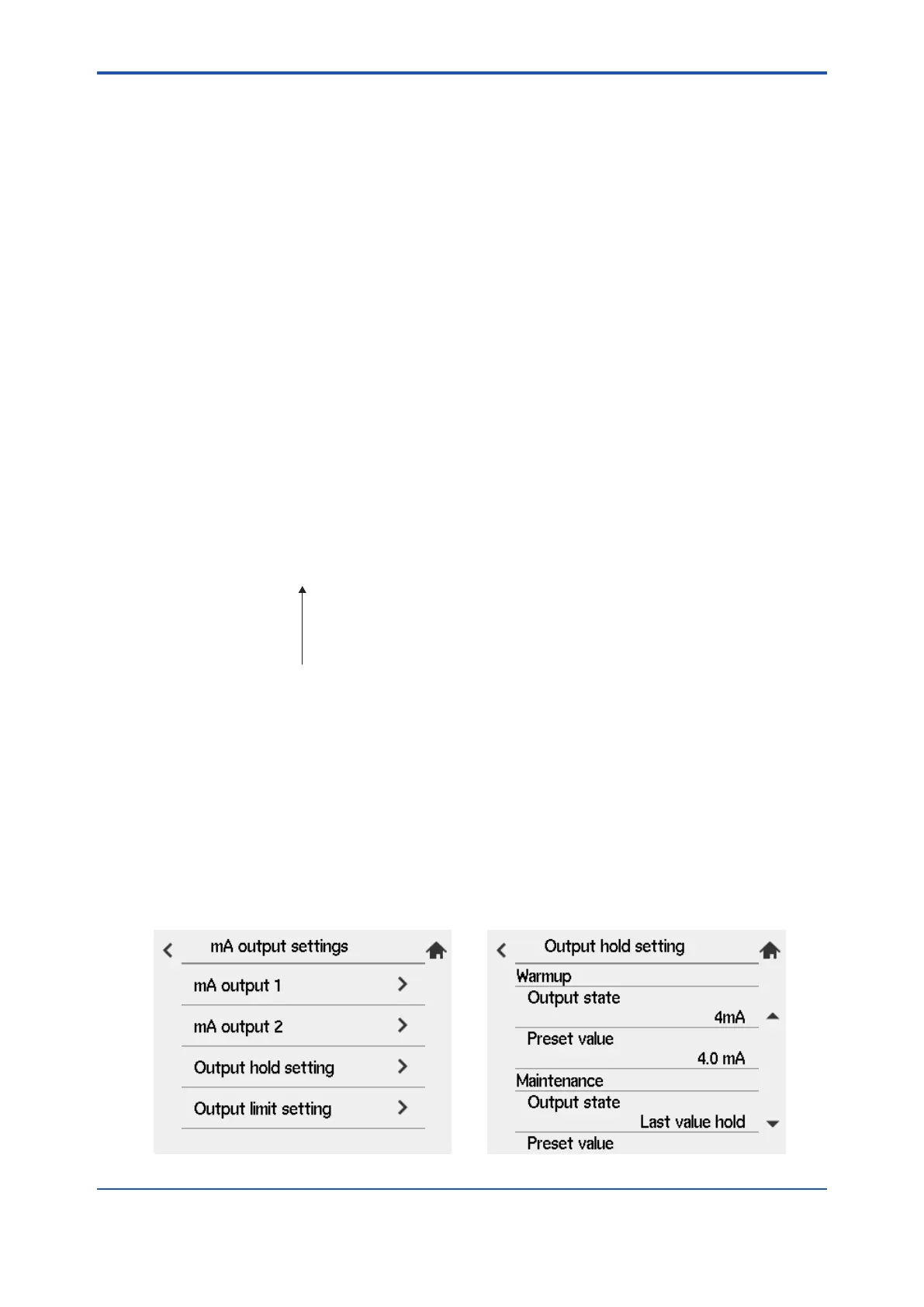
8.2.3 mA output settings
(1) “Converter menu” > “Setting”
(2) Select “mA output settings”.
(3) Select “Output hold setting”.
calibration/blow back/simple cell resistance measurement, or Fault.
Figure 8.5 mA-outputs hold setting
 Loading...


