IM 05C01F12-41E
9
6. HARDWARE SPECIFICATIONS
•
Input: 1 point
•
Input type: Universal; can be selected by software
•
Input accuracy (at 23 ±2°C ambient temperature)
•
Thermocouple: ±2°C ±1digit
However,
•
±4°C for thermocouple input –200 to –100°C
•
±3°C for thermocouple input –100 to 0°C
•
±5°C for types R and S (±9°C for 0 to 500°C)
•
±9°C for type B
(accuracy is not guaranteed for 0 to 400°C)
•
RTD: ±1°C ±1digit
•
Voltage(mV, V) : ±0.3% ±1digit
•
Sampling period for measured value input: 500ms
•
Burn-out detection: Functions for thermocouple or RTD input
(burn-out upscale only; cannot be switched off)
•
Input resistance: 1MΩ or greater for thermocouple
or DC mV input. Approx. 1MΩ for DC V input
•
Maximum allowable signal source resistance :
250
Ω
for thermocouple or DC mV input
2k
Ω
for DC V input
•
Maximum allowable wiring resistance for RTD input:
10Ω/wire (The resistance values of three wires must be the same.)
•
Allowable input voltage: ±10V DC for thermocouple or DC mV input
±20V DC for DC V input
•
Noise rejection ratio:
Normal mode noise: Min. 40dB
(50/60Hz)
Common mode noise: Min. 120dB
(Min. 90dB for DC V input)
•
Error of reference junction compensation:±1.5°C (at 15-35°C)
±2.0°C (at 0-50°C)
The reference junction compensation cannot be switched off.
•
Applicable standards:
Thermocouple and resistance temperature detector(RTD)
JIS/IEC/DIN (ITS90)
SP (target setpoint) will be output in 3 seconds
after the change.
•
Output: 1 point
•
Output type: Current output
Output signal: 4 to 20mA
current output
Maximum load resistance: 600Ω
Output accuracy: ±0.3% of span
(at 23±2°C ambient temperature)
Measured Value (PV) Input
Alarm Functions
Manual Setting (SP) Output
•
Output signal: Measured value in 4-20mA DC,
can be scaled.
•
Maximum load resistance: 600Ω
•
Output accuracy: ±0.3% of span
(at 23±2°C ambient temperature)
Retransmission Output
•
Safety: Conforms to IEC1010-1: 1990 and EN61010-1: 1992
Approved by CSA1010 for installation category CAT II (IEC1010-1)
Certified for UL508 (pending)
•
EMC standards: Complies with
EN61326
The UD300 series manual setters conform to the standards
specified under the following conditions.
•
All wires except those for the power supply and
relay contact output terminals are shielded.
•
The manual setter does not fluctuate more than
20% even when noise is applied.
Safety and EMC Standards
■Normal Operating Conditions
•
Warm-up time: At least 30 minutes
•
Ambient temperature:0-50°C (0-40°C when
mounted side-by-side)
•
Rate of change of temperature: 10°C/h or less
•
Ambient humidity: 20-90% RH (no condensation allowed)
•
Magnetic field: 400A/m or less
•
Continuous vibrations of 5 to 14Hz: Amplitude of 1.2mm or less
•
Continuous vibrations of 14 to 150Hz: 4.9m/s
2
(0.5G) or less
•
Short-period vibrations: 14.7m/s
2
(1.5G) for 15 seconds or less
•
Shock: 98m/s
2
(10G) for 11 milliseconds or less
•
Mounting angle: Upward incline of up to 30
degrees; downward incline is not allowed.
•
Altitude: 2000m or less above sea level
■
Maximum Effects from Operating Conditions
(1) Temperature effects
•
Thermocouple, DC mV and DC V input: ±2µV/°C
or ±0.02% of F.S./°C, whichever is larger
•
Resistance temperature detector: ±0.05°C/°C
•
Analog output: ±0.05% of F.S./°C
(2) Effect from fluctuation of power supply voltage
(within rated voltage range)
•
Analog input: ±0.2µV/V or ±0.002% of F.S./V,
whichever is larger
•
Analog output: ±0.05% of F.S. /V
■
Transportation and Storage Conditions
•
Temperature: –25 to 70°C
•
Humidity: 5 to 95% RH (no condensation allowed)
•
Shock: Package drop height 90cm (when packed in
the dedicated package)
Environmental Conditions
■
Alarm Functions
•
Alarm types: 22 types
(waiting action can be set by software):
PV high limit, PV low limit, Deviation high
limit, Deviation low limit, De-energized on
deviation high limit, De-energized on deviation
low limit, Deviation high and low limits,
Deviation within high and low limits, De-
energized on PV high limit, De-energized on
PV low limit, Fault diagnosis output, FAIL
output
•
Alarm output: 2 relay contacts
Relay contact capacity: 1A at 240V AC or 1A
at 30V DC (with resistance load)
(COM terminal is common)
Note: The alarm output relays cannot be replaced by users
Construction, Mounting, and Wiring
•
Construction: Dust-proof and
splash-proof front
panel (compliant with IP65 [Model UD310] and
IP55 [Models UD320 and 350]). Splash-proof
construction is not available for side-by-side close
mounting.
•
Casing: ABS resin and polycarbonate
•
Case color: Black
•
Weight: UD310 - approx. 200g
UD320 - approx. 300g
UD350 - approx. 400g
•
Mounting: Flush panel mounting
•
Wiring: Screw terminals
Power Supply and Isolation
■
Power Supply
Note 1:
The primary terminals are the power supply terminals and
alarm output terminals.
The secondary terminals are the analog input and output terminals.
Note 2: The withstanding voltage is specified as 2300 V AC
per minute to provide a margin of safety.
Note 3: AC/DC 24V terminals are secondary terminals.
Maximum power consumption
Voltage
Frequency
Between primary terminals
and secondary terminals
(See Notes 1 and 3.)
Between primary terminals
and secondary terminals
(See Notes 1 and 3.)
50 or 60Hz
Non-volatile memory
1500V AC
for 1 minute
(See Note 2.)
20MΩ or more at
500V DC
Memory
Withstanding
voltage
Insulation
resistance
Power
supply
Rated at 100-240VAC (±10%)
AC/DC 24V, 20 to 29V of
allowable range when
⬙/V24⬙ is specified.
8VA max. (4W max.)
3W max. when
⬙/V24⬙ is specified.
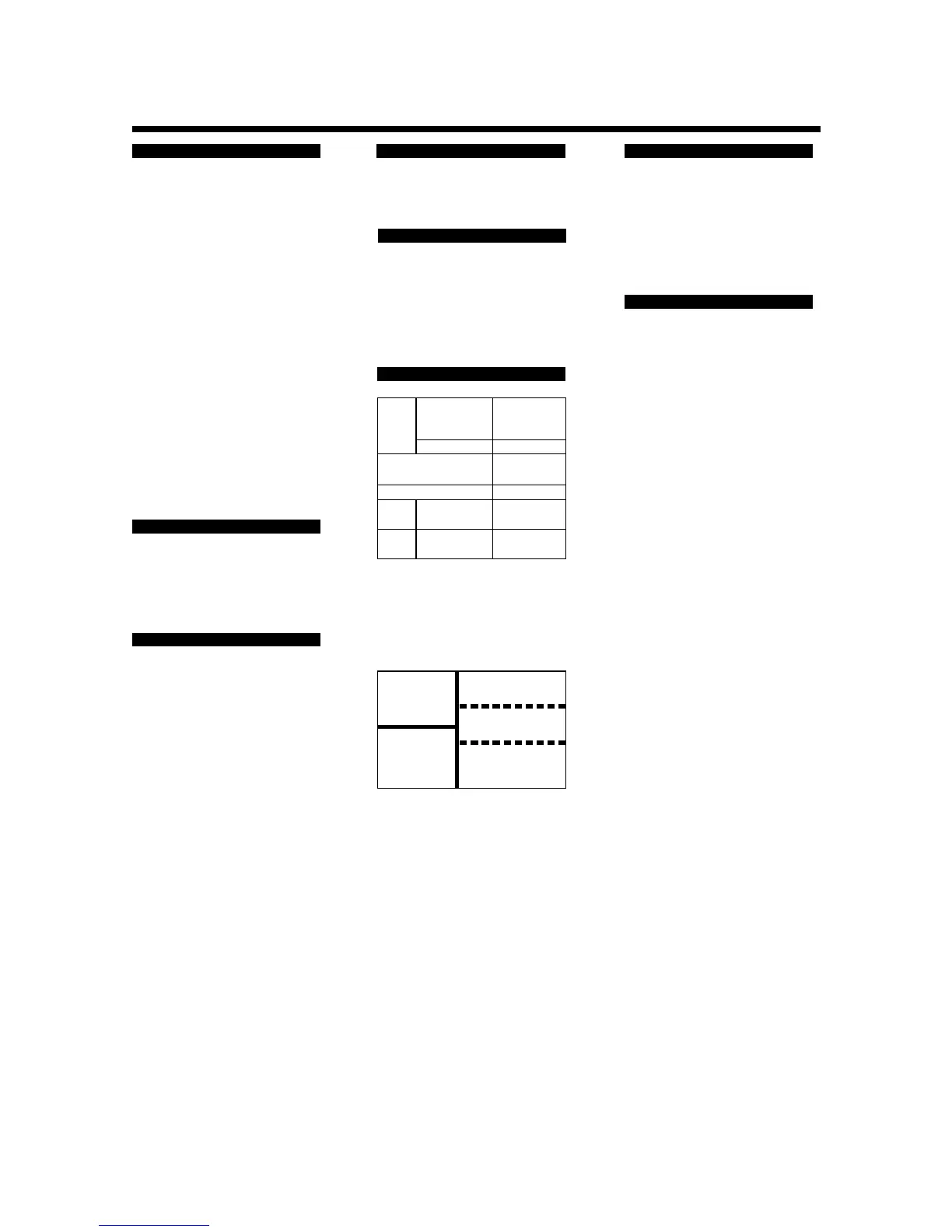
■ Isolation
The bold lines below indicate reinforced isolation, and
the broken line indicates functional isolation.
Note: The measured value input terminals is isolated from the
internal circuit.
•
Measured value input
terminals
•
Internal circuit
•
Alarm output
terminals
(2 relay contacts)
•
Manual setting output
terminals :
4-20 mA
•
Retransmission output
terminals :
4-20 mA
•
Power supply
terminals
(100-240V AC)
•
Power supply
terminals AC/DC 24V
(When ⬙/V24⬙ is specified)

 Loading...
