IM 05C01F12-41E
19
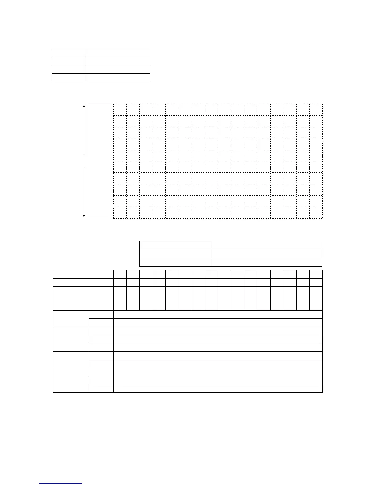
Device name
Program name
Model name
Serial No.
Segment No.
Target setpoint (SP)
Segment time (TM)
(hour.minute or minute.second)
Use the TMU setup parameter to set
the time unit.
EON1
EOF1
AL1
A1
HY1
EON2
EOF2
AL2
A2
HY2
Time event 1
(EV1=1)
PV event 1
(EV1=0)
Time event 2
(EV2=1)
PV event 2
(EV2=0)
1 2 3 4 5 6 7 8 9 10 11 12 13 14 15 16
100%
RH
Maximum value of
measured input
range (scale)
Minimum value of
measured input
range (scale)
(Note) Displayed only for DC voltage input.
0%
RL
(Note)
(Note)
Measured Input
Range (Scale)
Starting target setpoint value (SSP)
Start code (STC)
Junction code (JC)
■ Program Pattern Setting Table

 Loading...
