<12. Troubleshooting>
12-7
IM 11M12G01-02EN 1sh Edition : Mar. 25, 2021-00
(5) Alarms 201 and 202: Zero correction ratio high and low alarm
Occurs when the zero-point compensation ratio exceeds 100 ± 30% in the auto calibration or
semi-auto calibration (see section:
“9.1.4 Compensation”). Possible causes of this are as
follows.
• Zero gas oxygen concentration does not match the zero gas concentration value setup in
“setup of calibration”, or the span gas was used as the zero gas.
• The sensor assembly is damaged and the cell electromotive force is faulty.
<Searching for the cause of the error and remedy>
(1) Check the following and perform calibration again. If the status is not correct, correct it.
1. When “Zero gas concentration” is turned Display in setup of calibration, is set value
matched with the actually used zero gas concentration?
2. Are calibration gas pipes installed to prevent zero air leakage?
(2) If calibration is performed again and there is no alarm, it is probable that calibration condition
was incorrect as the reason for the alarm in the results calibration. In this case, no special
(3) If the alarm is triggered again after calibration, the sensor assembly may be degraded or
damaged. It must be replaced with a new cell (sensor), but do the following before replacing.
1. Running calibration turns Display the cell electromotive force in Trend screen.
theoretical oxygen-concentration. The theoretical value of cell electromotive force can be
but consider it to be approximately ± 10 mV .
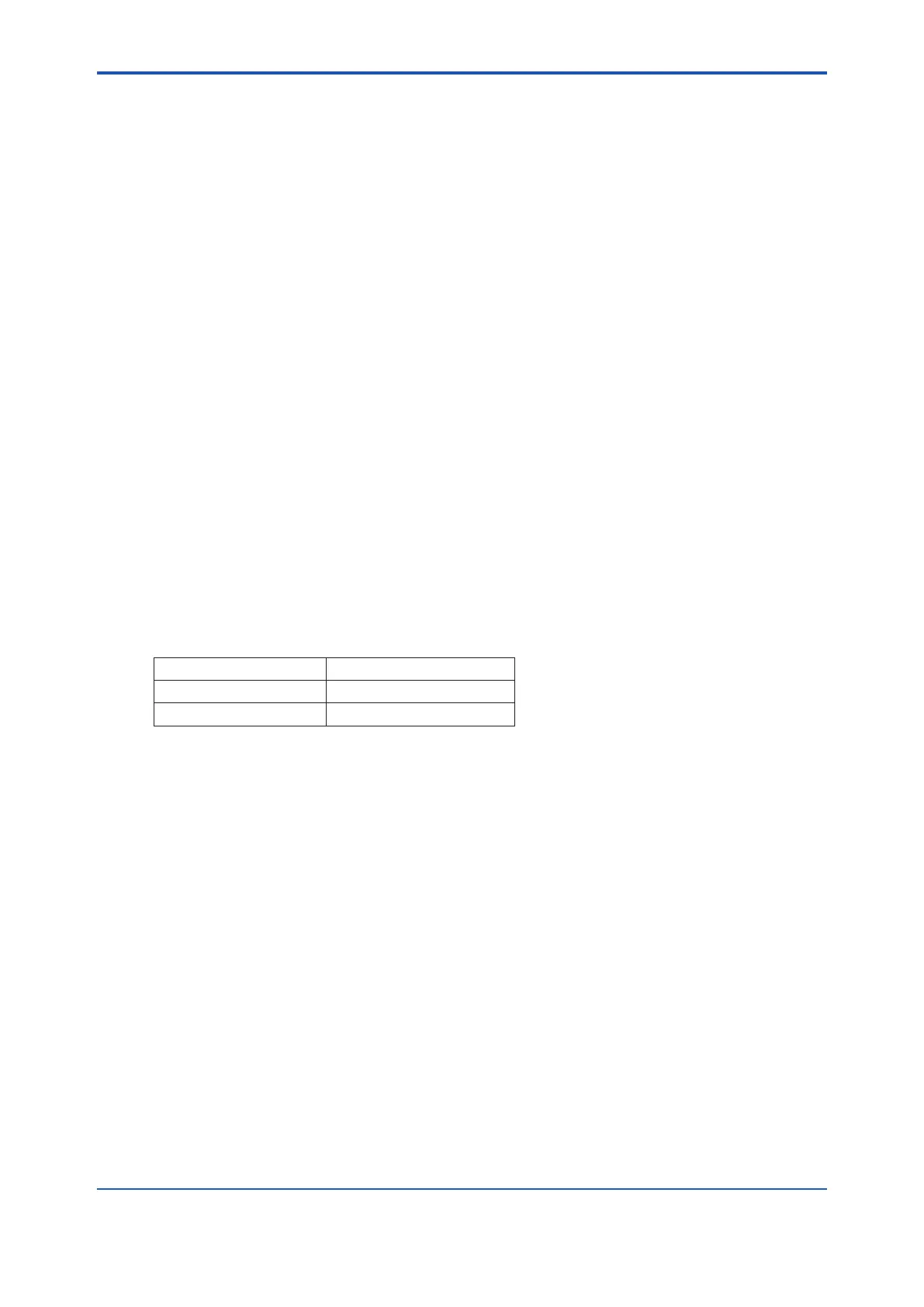
Table 12.3 Oxygen Concentration and Cell Electromotive Force
Oxygen concentration Cell electromotive force
1% O
2
67.1 mV
21% O
2
0 mV
(4) Check the following steps to see if any degradation or damage to the sensor assembly
caused by the alarm occurred suddenly during this calibration.
1. Select the detailed screen from the “Converter Menu” to display the log information.
2. By selecting “Zero/Span Calibration History”, you can check the values of the span point
correction rate and zero point correction rate, so you can see the change in degradation of
the cell (sensor).
(5) If the sensor assembly deteriorates abruptly, the check valve that prevents moisture from
entering the calibration gas piping from inside the furnace may be defective. When gas
from the furnace enters the calibration gas line, it cools and becomes condensed water
and accumulates in the piping. This may have been blown into the sensor assembly by the
calibration gas during calibration and the sensor assembly has been damaged by the rapid
cooling of the cell.
(6) If the sensor assembly is gradually deteriorated, check the status of the sensor assembly by
following the procedure below.
1. Select the detailed screen from the “Sensor Menu” and check “Cell Resistance”. New
2. Check the “Cell health level”. Good cells (sensors) indicate “lifetime > 1 year”
 Loading...


