EasyManua.ls Logo

York 13 Seer-TCJD User Manual

York 13 Seer-TCJD
16 pages
To Next Page IconTo Next Page
Page #1 background imageLoading...
Page #1 background image
Johnson Controls Unitary Products 835964-UIM-A-0112
R-410A
OUTDOOR SPLIT-SYSTEM
AIR CONDITIONING
MODELS: 13 & 14.5 SEER -
TCG(D,F)/GCGD/TCJ(D,F)/YCJ(D,F) SERIES
1.5 TO 5 TONS – 1 & 3 PHASE
INSTALLATION MANUAL
®
LIST OF SECTIONS
GENERAL . . . . . . . . . . . . . . . . . . . . . . . . . . . . . . . . . . . . . . . . . . . . . ‘1
SAFETY . . . . . . . . . . . . . . . . . . . . . . . . . . . . . . . . . . . . . . . . . . . . . . . .1
UNIT INSTALLATION . . . . . . . . . . . . . . . . . . . . . . . . . . . . . . . . . . . . .2
ORIFICE INSTALLATION . . . . . . . . . . . . . . . . . . . . . . . . . . . . . . . . . .5
TXV INSTALLATION . . . . . . . . . . . . . . . . . . . . . . . . . . . . . . . . . . . . . .5
EVACUATION . . . . . . . . . . . . . . . . . . . . . . . . . . . . . . . . . . . . . . . . . . 5
SYSTEM CHARGE . . . . . . . . . . . . . . . . . . . . . . . . . . . . . . . . . . . . . . 6
ELECTRICAL CONNECTIONS . . . . . . . . . . . . . . . . . . . . . . . . . . . . . 7
INSTRUCTING THE OWNER . . . . . . . . . . . . . . . . . . . . . . . . . . . . . 13
WIRING DIAGRAM . . . . . . . . . . . . . . . . . . . . . . . . . . . . . . . . . . . . . 14
LIST OF FIGURES
Typical Installation . . . . . . . . . . . . . . . . . . . . . . . . . . . . . . . . . . . . . . . .2
Installation of Vapor Line . . . . . . . . . . . . . . . . . . . . . . . . . . . . . . . . . . .3
Underground Installation . . . . . . . . . . . . . . . . . . . . . . . . . . . . . . . . . . .3
Heat Protection . . . . . . . . . . . . . . . . . . . . . . . . . . . . . . . . . . . . . . . . . .4
Orifice Installation . . . . . . . . . . . . . . . . . . . . . . . . . . . . . . . . . . . . . . . . .5
Outdoor Unit Control Box (Single Phase) . . . . . . . . . . . . . . . . . . . . . .7
Outdoor Unit Control Box (Three Phase) . . . . . . . . . . . . . . . . . . . . . . .7
Typical Field Wiring (Air Handler / Electrical Heat) (Single-Phase) . . .8
Typical Field Wiring (Air Handler / Electrical Heat) (Three-Phase) . . . 8
Thermostat Chart - Single Stage AC with PSC Air Handler . . . . . . . . 9
Thermostat Chart - Single Stage AC with PSC Air Handler . . . . . . . 10
Thermostat Chart - Single Stage AC with PSC Furnace . . . . . . . . . 11
Thermostat Chart - Single Stage AC with PSC Furnace . . . . . . . . . 12
Wiring Diagram - Single Phase . . . . . . . . . . . . . . . . . . . . . . . . . . . . . 14
Wiring Diagram - Three Phase . . . . . . . . . . . . . . . . . . . . . . . . . . . . . 15
LIST OF TABLES
Application Limitations . . . . . . . . . . . . . . . . . . . . . . . . . . . . . . . . . . . . .2 R-410A Saturation Properties . . . . . . . . . . . . . . . . . . . . . . . . . . . . . . . 7
SECTION I: GENERAL
The outdoor units are designed to be connected to a matching indoor
coil with sweat connect lines. Sweat connect units are factory charged
with refrigerant for a matching indoor coil plus 15 feet of field-supplied
lines.
The refrigerant charge may need to be changed for some indoor-out-
door unit combinations, elevation differences or total line lengths. Refer
to Application Data covering “General Piping Recommendations and
Refrigerant Line Length” (Part Number 247077).
SECTION II: SAFETY
This is a safety alert symbol. When you see this symbol on
labels or in manuals, be alert to the potential for personal
injury.
Understand and pay particular attention to the signal words DANGER,
WARNING, or CAUTION.
DANGER indicates an imminently hazardous situation, which, if not
avoided, will result in death or serious injury
.
WARNING indicates a potentially hazardous situation, which, if not
avoided, could result in death or serious injury
.
CAUTION indicates a potentially hazardous situation, which, if not
avoided may result in minor or moderate injury
. It is also used to
alert against unsafe practices and hazards involving only property dam-
age.
INSPECTION
As soon as a unit is received, it should be inspected for possible dam-
age during transit. If damage is evident, the extent of the damage
should be noted on the carrier’s delivery receipt. A separate request for
inspection by the carrier’s agent should be made in writing. See Local
Distributor for more information.
Requirements For Installing/Servicing R-410A Equipment
Gauge sets, hoses, refrigerant containers, and recovery system
must be designed to handle the POE type oils, and the higher
pressures of R-410A.
Manifold sets should be high side and low side with low side
retard.
All hoses must have a 700 psig service pressure rating.
Leak detectors should be designed to detect HFC refrigerant.
Recovery equipment (including refrigerant recovery containers)
must be specifically designed to handle R-410A.
Do not use an R-22 TXV.
A liquid-line filter drier is required on every unit.
This product must be installed in strict compliance with the
enclosed installation instructions and any applicable local, state,
and national codes including, but not limited to building, electrical,
and mechanical codes.
R-410A systems operate at higher pressures than R-22 systems.
Do not use R-22 service equipment or components on R-410A
equipment. Service equipment
Must Be Rated for R-410A.
Improper installation may create a condition where the operation of
the product could cause personal injury or property damage.
Improper installation, adjustment, alteration, service or mainte-
nance can cause injury or property damage. Refer to this manual
for assistance or for additional information, consult a qualified con-
tractor, installer or service agency.
Question and Answer IconNeed help?

Do you have a question about the York 13 Seer-TCJD and is the answer not in the manual?

York 13 Seer-TCJD Specifications

General IconGeneral
BrandYork
Model13 Seer-TCJD
CategoryAir Conditioner
LanguageEnglish

Summary

General

Safety

Explains DANGER, WARNING, and CAUTION signal words for hazard identification.

Safety Signal Words

Explains DANGER, WARNING, and CAUTION signal words for hazard identification.

Installation Compliance Caution

Emphasizes strict compliance with installation instructions and codes.

R-410A Pressure Caution

Warns about higher R-410A pressures and using compatible service equipment.

Improper Installation Warning

Warns that improper installation can cause injury or property damage.

Unit Limitations

Operational Limitations

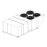
Covers outdoor unit installation, air stream restrictions, temperature conditions, and line length.

Multiple Unit Spacing

Specifies minimum spacing for multiple outdoor unit installations.

Unit Installation

Installation Location

Details site selection, clearances, and structural support for outdoor units.

Add-On Replacement/Retrofit

Outlines steps for replacing existing R-22 systems with R-410A.

Ground Installation

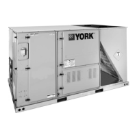
Specifies requirements for installing the unit on a solid base and maintaining clearances.

Roof Installation

Details structural support requirements for roof-mounted units.

Liquid Line Filter-Drier

Information on the liquid line filter-drier, including replacement parts.

Filter-Drier Replacement Caution

Warns against using incorrect filter-driers, which can damage equipment.

Piping Connections

Guidelines for connecting refrigerant lines, including tubing types and sizes.

R-410A Refrigerant Caution

Highlights R-410A's higher pressure and the need for compatible equipment.

Suction-Line Filter-Drier Warning

Prohibits suction-line filter-driers in R-410A liquid lines due to fire/injury risk.

Line Installation Precautions

Details proper methods for installing refrigerant lines, including bends, insulation, and support.

Brazing Line Precautions

Covers brazing procedures, material types, and ensuring an internally clean system.

Dry Nitrogen Brazing Caution

Advises on using dry nitrogen during brazing to prevent oxidation.

Brazing Service Valve Precautions

Steps to protect service valves and prevent damage during brazing.

Service Valve Operation Warning

Explains that service access ports are not backseated valves and warns of O-ring damage.

Furnace Coil Installation Caution

Warns about pressure build-up in furnace coils if refrigerant lines are not attached.

Manifold Gauge Caution

Advises against connecting manifold gauges unless trouble is suspected due to refrigerant loss.

Brazed Connection Warning

Prohibits repairing brazed connections while the system is under pressure.

Orifice Installation

Orifice Installation Warning

Warns that failure to install the valve core can lead to total refrigerant loss.

Valve Type Importance

Specifies that only 1TVM900 series valves are to be used.

TXV Installation

TXV Model Caution

Notes that TXV models may require a hard start kit.

TXV and Schrader Core Warning

States Schrader valve cores must not be installed with TXV installations.

Evacuation

Evacuation

Procedures for evacuating the system to 500 microns or less.

System Charge

System Charge

Details how to determine and add refrigerant charge to the system.

Pump Charge Warning

Prohibits pumping total system charge into the outdoor unit for service.

Refrigerant Charging Caution

States that refrigerant charging should be done by a qualified contractor.

Compressor Damage Caution

Warns that improper charging can damage the compressor.

Superheat Charging Method (Piston Indoor)

Explains how to charge the system using the superheat method for piston indoor units.

Subcooling Charging Method (TXV Indoor)

Details charging the system using the subcooling method for TXV indoor units.

Refrigerant Venting Caution

Reiterates the illegality of venting refrigerant during service.

Electrical Connections

Electrical General Information and Grounding

Covers checking electrical supply, power wiring, and grounding requirements.

Field Wiring Caution

Mandates using copper conductors only and adhering to electrical codes.

Power Wiring Connections

Steps for making power wiring connections, including disconnect switches and fuses.

Control Wiring Connections

Instructions for routing and connecting low voltage control wiring.

Thermostat Installation Notice

Advises on proper thermostat mounting location and sealing drafts.

Instructing the Owner

Routine Maintenance

Details recommended maintenance tasks for the unit.

Coil Cleaner Notice

Warns against using specific coil cleaners that can damage the aluminum coil.

Refrigerant Venting Caution

Reiterates the illegality of venting refrigerant during service.

Wiring Diagram

Electrical Shock Caution

Advises turning off power to prevent shock and equipment damage.

Notes

Related product manuals