EasyManua.ls Logo

York 2ET04700224 - User Manual

York 2ET04700224
12 pages
Print Icon
To Next Page IconTo Next Page
Loading...
USER GUIDE
Programmable Thermostat - 2ET04700224 / 324 / 424
Roof - Top units
THERMOSTATS
Question and Answer IconNeed help?

Do you have a question about the York 2ET04700224 and is the answer not in the manual?

Summary

Specifications

General Features

Outlines the key functionalities and operational capabilities of the thermostat.

Installation

Set Subbase DIP Switches

Configuration guide for subbase DIP switches to match system requirements.

Wiring

Connections for 2 ET04700224

Wiring diagram and terminal connections for the 2ET04700224 model.

Connections for 2 ET04700324

Wiring diagram and terminal connections for the 2ET04700324 model.

Connections for 2 ET04700424

Wiring diagram and terminal connections for the 2ET04700424 model.

Program the Thermostat

Set Program Times

Instructions for programming occupied and unoccupied start times for each day.

Set Program Temperature Setpoints

How to set desired temperature setpoints for occupied and unoccupied periods.

Overview

This document provides a comprehensive user guide for the York Programmable Thermostat, specifically models 2ET04700224, 2ET04700324, and 2ET04700424, designed for roof-top units. The guide covers installation, wiring, and programming, ensuring optimal operation and energy efficiency.

Function Description

The York Programmable Thermostat is a sophisticated control device designed to manage heating and cooling equipment in single-stage and multistage HVAC applications. Its primary function is to maintain desired indoor temperatures according to programmed schedules, offering both comfort and energy savings. The thermostat supports two occupied and two unoccupied periods per day, allowing for precise temperature control tailored to building occupancy patterns. It features individual temperature setpoints for occupied heat, occupied cool, unoccupied heat, and unoccupied cool, providing flexibility in managing different comfort requirements.

A key feature is the Proportional Plus Integral (P+I) control, which effectively eliminates temperature fluctuations and prevents unauthorized tampering with settings. This advanced control algorithm ensures stable and consistent indoor temperatures, enhancing occupant comfort. For heat pump systems, the thermostat incorporates a specific algorithm to optimize performance.

The thermostat also includes an "Intelligent Recovery" feature, a Honeywell trademark, which optimizes the start time of heating and cooling equipment based on the building's load. During recovery from an unoccupied to an occupied setting, the control point ramps up gradually (3°C per hour for conventional systems, 2°C per hour for heat pumps). This gradual ramp-up maximizes the use of the more economical first-stage heat, minimizing reliance on typically more expensive second-stage heating. This intelligent approach not only saves energy but also reduces drafts from low-temperature discharge air during occupied periods and extends equipment life by reducing cycling.

The "Intelligent Fan" feature energizes the fan only when there is a call for heating or cooling, although it can be configured to run continuously during occupied mode for enhanced air circulation. Automatic heat/cool changeover is also supported, simplifying operation for users.

Usage Features

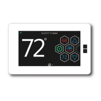
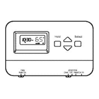
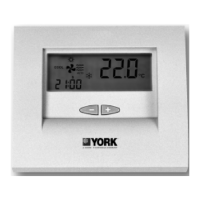
The thermostat offers a user-friendly interface with a keyboard located behind a flip-up cover, providing 16 keys for setting, reviewing, and modifying programmed times and temperatures. The Liquid Crystal Display (LCD) clearly shows the day, time, temperature, and the current programming period.

Programming the thermostat involves several steps:

  1. Setting Current Time/Day: Users can easily adjust the current time and day using the CLOCK and DAY keys, along with the + or - keys. The display supports both 12-hour and 24-hour clock formats, selectable via DIP switches.
  2. Setting Program Times: The thermostat allows for two occupied and two unoccupied periods per day, with programming times in ten-minute intervals. Users can select a specific day, set the occupied start time, and then the unoccupied start time. If a start time is not needed, it can be cleared using the CLEAR START TIME key. The program indicator on the LCD guides the user through the occupied and unoccupied settings.
  3. Copying a Day: To simplify programming, users can copy the schedule from one day to another, reducing repetitive input.
  4. Setting Program Temperature Setpoints: Individual temperature setpoints can be configured for occupied heat, occupied cool, unoccupied heat, and unoccupied cool. The setpoint range is 7°C (unoccupied heat) to 35°C (unoccupied cool), with a minimum 1°C deadband between heating and cooling setpoints. The occupied heat setpoint must be at least 1°C less than the occupied cool setpoint.
  5. Setting Operating Display: The LCD can be toggled to show either time or temperature by pressing the DISPLAY key.
  6. Clearing Start Time: Specific start times can be cleared if a period is no longer required.

The thermostat also includes convenient override features for temporary changes:

  • 3 Hour Occupied Override: This feature allows users to temporarily override the unoccupied program for three hours, useful for late work, weekends, or holidays. The unoccupied temperature setting changes to the occupied setpoint. An additional option allows adjusting the occupied setpoint by a preassigned value (0 to 3°C) using the + or - keys, providing flexibility in temporary comfort levels.
  • Continuous Unoccupied Override (CONT UNOC): This feature holds the temperature at the unoccupied setpoint indefinitely until the DISPLAY or CONT UNOC key is pressed again. This is ideal for extended periods when the area will be closed, such as long holidays.

For enhanced security and to prevent unauthorized changes, the thermostat supports locking setpoints and schedules, which can be enabled by disabling the keyboard via a DIP switch. However, even with the keyboard disabled, users can still review programs, perform overrides, and make clock changes.

Maintenance Features

The thermostat is designed with ease of maintenance in mind, particularly concerning power and battery management.

  • Battery Backup: The device operates on 24 Vac power, but a 9-volt alkaline battery can be installed to maintain the program during power outages. While not essential for operation, the battery ensures that programmed settings are retained. Without the battery, the system will revert to default setpoints after a power loss. The battery compartment is easily accessible on the back of the display, and installation requires observing polarity. The battery provides up to 60 hours of backup.
  • Installation and Wiring: The guide provides detailed instructions for new installations, including mounting the subbase or wallplate, setting subbase DIP switches, and connecting ribbon cables. Color-coded thermostat cable with at least one conductor per wiring terminal is recommended, with extra conductors for future needs. Proper cable routing away from electrical interference is emphasized.
  • DIP Switches: Both subbase and display DIP switches are crucial for configuring the thermostat to match the specific HVAC system and desired features. These switches allow customization for single-stage or multistage operation, P+I control, fan operation (cool only or heat and cool), sensor type (internal or remote), display units (°F or °C), and clock format (12-hour or 24-hour).
  • Mini-Jumper: A mini-jumper on the back of the display allows switching between conventional system control and heat pump algorithm, ensuring compatibility with different HVAC setups. This setting must be done before installing batteries.
  • Power Disconnection: For safety during installation or maintenance, the guide stresses the importance of disconnecting the 24 Vac power supply and removing the battery before connecting ribbon cables to prevent electrical shock and equipment damage.

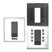
The modular design, with a separate subbase and display unit connected by ribbon cables, facilitates installation and potential replacement of components. The use of Allen head screws to secure the display to the subbase ensures a firm and reliable connection.

York 2ET04700224 Specifications

General IconGeneral
Model2ET04700224
Hold FeatureYes
TypeDigital
Voltage24 VAC
DisplayLCD
Power SourceHardwired

Related product manuals