EasyManua.ls Logo

York Affinity BHZ024-060 User Manual

York Affinity BHZ024-060
24 pages
To Next Page IconTo Next Page
Page #1 background imageLoading...
Page #1 background image
R-410A
AFFINITY SERIES
BHZ024-060
2-5 Ton
ISO 9001
Certified Quality
Management System
268721-YIM-C-0908
TABLE OF CONTENTS
General . . . . . . . . . . . . . . . . . . . . . . . . . . . . . . . . . . . . . . . . . . 1
Installation . . . . . . . . . . . . . . . . . . . . . . . . . . . . . . . . . . . . . . . . 3
Limitations. . . . . . . . . . . . . . . . . . . . . . . . . . . . . . . . . . . . . . 3
Location. . . . . . . . . . . . . . . . . . . . . . . . . . . . . . . . . . . . . . . . 4
Rigging And Handling . . . . . . . . . . . . . . . . . . . . . . . . . . . . . 4
Ductwork . . . . . . . . . . . . . . . . . . . . . . . . . . . . . . . . . . . . . . . 7
Roof Curb . . . . . . . . . . . . . . . . . . . . . . . . . . . . . . . . . . . . . . 7
Filters . . . . . . . . . . . . . . . . . . . . . . . . . . . . . . . . . . . . . . . . . 7
Condensate Drain . . . . . . . . . . . . . . . . . . . . . . . . . . . . . . . . 8
Service Access . . . . . . . . . . . . . . . . . . . . . . . . . . . . . . . . . . 8
Thermostat . . . . . . . . . . . . . . . . . . . . . . . . . . . . . . . . . . . . . 8
Power And Control Wiring. . . . . . . . . . . . . . . . . . . . . . . . . . 8
Compressors. . . . . . . . . . . . . . . . . . . . . . . . . . . . . . . . . . . 12
Phasing. . . . . . . . . . . . . . . . . . . . . . . . . . . . . . . . . . . . . . . 12
Airflow Performance . . . . . . . . . . . . . . . . . . . . . . . . . . . . . . . 13
Operation . . . . . . . . . . . . . . . . . . . . . . . . . . . . . . . . . . . . . . . 15
Anti-short Cycle Timer. . . . . . . . . . . . . . . . . . . . . . . . . . . . 15
Cooling Sequence Of Operations . . . . . . . . . . . . . . . . . . . 15
Heating Sequence Of Operations. . . . . . . . . . . . . . . . . . . 16
Maintenance . . . . . . . . . . . . . . . . . . . . . . . . . . . . . . . . . . . . . 18
Normal Maintenance. . . . . . . . . . . . . . . . . . . . . . . . . . . . . 18
Troubleshooting . . . . . . . . . . . . . . . . . . . . . . . . . . . . . . . . . . 18
Typical Wiring Diagrams. . . . . . . . . . . . . . . . . . . . . . . . . . 19
LIST OF TABLES
1 Unit Limitations . . . . . . . . . . . . . . . . . . . . . . . . . . . . . . . . . 3
2 Unit Accessory Weights . . . . . . . . . . . . . . . . . . . . . . . . . . 5
3 Unit Dimensions Front . . . . . . . . . . . . . . . . . . . . . . . . . . . . 5
4 Unit Clearances . . . . . . . . . . . . . . . . . . . . . . . . . . . . . . . . . 5
5 Electrical Data . . . . . . . . . . . . . . . . . . . . . . . . . . . . . . . . . 10
6 Physical Data . . . . . . . . . . . . . . . . . . . . . . . . . . . . . . . . . 11
7 Side Duct Application . . . . . . . . . . . . . . . . . . . . . . . . . . . 13
8 Bottom Duct Application . . . . . . . . . . . . . . . . . . . . . . . . . 13
9 Additional Static Resistance . . . . . . . . . . . . . . . . . . . . . . 14
10 Electric Heat Minimum Supply Air . . . . . . . . . . . . . . . . . 15
11 Indoor Blower Specifications . . . . . . . . . . . . . . . . . . . . . . 15
12 Electric Heat Multipliers . . . . . . . . . . . . . . . . . . . . . . . . . 15
13 Demand Defrost Selection . . . . . . . . . . . . . . . . . . . . . . . 16
14 Thermostat Signals (Single Phase Units) . . . . . . . . . . . . 17
15 Thermostat Signals (Three Phase Units) . . . . . . . . . . . . 17
LIST OF FIGURES
1 Component Location . . . . . . . . . . . . . . . . . . . . . . . . . . . . 3
2 Unit 4 Point Load Weight . . . . . . . . . . . . . . . . . . . . . . . . . 4
3 Unit Dimensions . . . . . . . . . . . . . . . . . . . . . . . . . . . . . . . . 5
4 Dimensions Front and Bottom . . . . . . . . . . . . . . . . . . . . . 6
5 Dimensions Back and Bottom . . . . . . . . . . . . . . . . . . . . . 6
6 Roof Curb . . . . . . . . . . . . . . . . . . . . . . . . . . . . . . . . . . . . . 7
7 Typical Field Control Wiring Diagram . . . . . . . . . . . . . . . 9
8 Typical Field Power Wiring Diagram . . . . . . . . . . . . . . . . 9
9 Demand Defrost “Curve” Selection Jumper . . . . . . . . . . 16
10 R-410A Quick Reference Guide . . . . . . . . . . . . . . . . . . 22
General
YORK
®
Affinity Model BHZ units are factory assembled heat
pumps designed for outdoor installation on a roof top or a slab.
Field-installed electric heater accessories are available to
provide supplemental electric heat combined with electric
cooling and heating.
The units are completely assembled on rigid, removable base
rails. All piping, refrigerant charge, and electrical wiring is
factory installed and tested. The units require only electric
power and duct connections at the point of installation.
The electric heaters have nickel-chrome resistance wire
elements and utilize single point power connection.
Safety Considerations
This is a safety alert symbol . When you see this symbol on
labels or in manuals, be alert to the potential for personal injury.
Understand and pay particular attention the signal words
DANGER, WARNING or CAUTION.
DANGER indicates an imminently hazardous situation, which,
if not avoided, will result in death or serious injury
.
WARNING indicates a potentially hazardous situation, which,
if not avoided, could result in death or serious injury
.
CAUTION indicates a potentially hazardous situation, which, if
not avoided may result in minor or moderate injury
. It is also
used to alert against unsafe practices and hazards involving
only property damage.
Improper installation may create a condition where the
operation of the product could cause personal injury or
property damage. Improper installation, adjustment,
alteration, service or maintenance can cause injury or
property damage. Refer to this manual for assistance or
for additional information, consult a qualified contractor,
installer or service agency.
Question and Answer IconNeed help?

Do you have a question about the York Affinity BHZ024-060 and is the answer not in the manual?

York Affinity BHZ024-060 Specifications

General IconGeneral
ModelBHZ024-060
TypeHeat Pump
Cooling Capacity (BTU)24, 000 - 60, 000
Heating Capacity (BTU)24, 000 - 60, 000
RefrigerantR-410A
Compressor TypeScroll
Voltage208/230V
Phase1
DimensionsVaries by model
WeightVaries by model
StagesVariable Speed
Warranty10-year limited parts warranty

Summary

General Installation Guidelines

Installation, Limitations, and Location

Covers installation compliance, unit limits, and site selection procedures.

Rigging, Ductwork, and Filters

Procedures for unit handling, air duct connection, and filter installation.

Service Access, Thermostat, and Wiring

Details access points, thermostat setup, and electrical wiring requirements.

Safety and Hazard Awareness

Understanding Safety Signal Words

Explains DANGER, WARNING, and CAUTION for hazard recognition and injury prevention.

Safety Precautions and Compliance

General Safety and Code Compliance

Emphasizes strict adherence to codes and safe operating practices for installation.

Refrigerant Handling and System Safety

Covers safety for R-410A refrigerant and system pressure hazards.

Unit Nomenclature and Identification

Model Number Decoding

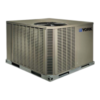
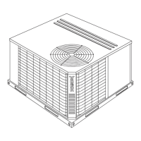
Explains the components and meaning of the unit's model number.

Installation Specifics

Unit Limitations and Requirements

Details unit operational limits and installation requirements.

Location and Rigging Guidelines

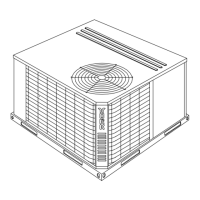
Provides guidelines for unit placement, lifting, and handling.

Required Unit Clearances

Specifies minimum clearances for unit operation and servicing.

Unit Physical Data

Unit Load Weight Distribution

Details on 4-point load weights for proper unit placement and support.

Unit Dimensions and Accessories

Unit Dimensions Front

Specifies the front dimensions of the unit for installation planning.

Unit Clearances Table

Provides a table of required clearances for operation and service.

Ductwork and Roof Curb Installation

Ductwork Connection Procedures

Instructions for connecting supply and return air ductwork to the unit.

Roof Curb Installation Guidelines

Guidance on correctly positioning the unit on a roof curb.

Filter Requirements and Maintenance

Details the importance of filters, their installation, and regular maintenance.

System Connections and Controls

Condensate Drain and Service Access

Instructions for condensate drain setup and access to service points.

Thermostat Installation and Wiring

Guidelines for thermostat placement and connecting control wires.

Power and Control Wiring Requirements

Outlines electrical wiring standards and requirements for unit power.

Wiring Diagrams

Typical Field Control Wiring Diagram

Illustrates typical wiring for thermostat and unit controls.

Typical Field Power Wiring Diagram

Illustrates typical wiring for unit electrical power supply.

Electrical Data

Electrical Data for Unit Sizes

Provides detailed electrical specifications for different unit sizes.

Physical and Performance Data

Unit Physical Data by Model

Details physical characteristics like dimensions and weight for each model.

Compressor and Phasing Information

Compressor Specifications and Oil

Information on compressor type, oil requirements, and handling precautions.

Three-Phase Compressor Phasing

Guidance on ensuring correct rotation for three-phase compressors.

Airflow Performance Data

Side Duct Airflow Performance

Tables showing airflow performance for side duct applications.

Bottom Duct Airflow Performance

Tables showing airflow performance for bottom duct applications.

Static Resistance Data

Additional Static Resistance Values

Data on static resistance added by components like economizers and filters.

Unit Operation and Controls

Anti-short Cycle Timer Function

Explains the function and bypass of the anti-short cycle timer.

Cooling Sequence of Operations

Details the operational steps during the cooling cycle.

Heating and Defrost Operation

Heating Sequence of Operations

Details the operational steps during the heating cycle.

Defrost Operation Logic

Explains the logic and timing of defrost cycles.

Safety Switch Operations

Describes the function of safety switches and lockout conditions.

Thermostat Signal Operations

Single Phase Thermostat Signals

Lists thermostat signals and their corresponding board functions for single-phase units.

Three Phase Thermostat Signals

Lists thermostat signals and their corresponding board functions for three-phase units.

Maintenance and Troubleshooting

Normal Maintenance Procedures

Outlines routine maintenance tasks for the unit.

Troubleshooting Components

Guidance on identifying and resolving common unit issues.

Wiring Diagrams

BHZ024-060 208/230-1-60 Wiring

Wiring diagram for single-phase, 208/230V models.

Three-Phase Wiring Diagrams

BHZ030-060 230-3-60 Wiring Diagram

Wiring diagram for three-phase, 230V models.

High Voltage Wiring Diagrams

BHZ030-060 460-3-60 Wiring Diagram

Wiring diagram for three-phase, 460V models.

R-410A Refrigerant Guide

R-410A System Servicing Requirements

Essential information and precautions for servicing R-410A systems.

Related product manuals